User Manual Compact I/O Isolated Analog Modules Catalog Numbers 1769-IF4I, 1769-OF4CI, 1769-OF4VI
Important User Information Solid-state equipment has operational characteristics differing from those of electromechanical equipment. Safety Guidelines for the Application, Installation and Maintenance of Solid State Controls (publication SGI-1.1 available from your local Rockwell Automation sales office or online at http://www.rockwellautomation.com/literature/) describes some important differences between solid-state equipment and hard-wired electromechanical devices.
Table of Contents Preface Who Should Use This Manual. . . . . . . . . . . . . . . . . . . . . . . . . . How to Use This Manual. . . . . . . . . . . . . . . . . . . . . . . . . . . . . . Manual Contents . . . . . . . . . . . . . . . . . . . . . . . . . . . . . . . . . Related Documentation. . . . . . . . . . . . . . . . . . . . . . . . . . . . Conventions Used in This Manual . . . . . . . . . . . . . . . . . . . . . .
ii Table of Contents Chapter 3 Module Data, Status, and Channel 1769-IF4I Input Module Addressing . . . . . . . . . . . . . . . . . . . . . . . . . 3-1 1769-IF4I Input Image . . . . . . . . . . . . . . . . . . . . . . . . . . . . . . . . . 3-2 Configuration for the Input Module 1769-IF4I Output Image . . . . . . . . . . . . . . . . . . . . . . . . . . . . . . . . 3-2 1769-IF4I Configuration File . . . . . . . . . . . . . . . . . . . . . . . . . . . . 3-2 1769-IF4I Input Data File . . . . . . . . . . . .
Table of Contents iii Chapter 5 Module Diagnostics and Troubleshooting Safety Considerations. . . . . . . . . . . . . . . . . . . . . . . . . . . . . . . . . . . . . . Indicator Lights . . . . . . . . . . . . . . . . . . . . . . . . . . . . . . . . . . . . . . . Activate Devices When Troubleshooting. . . . . . . . . . . . . . . . . . . Stand Clear of the Machine . . . . . . . . . . . . . . . . . . . . . . . . . . . . . . Program Alteration . . . . . . . . . . . . . . . . . . . . . . . . . . . . . . . . .
iv Table of Contents Appendix D Configure Modules in a Remote DeviceNet System with a 1769-ADN DeviceNet Adapter Overview. . . . . . . . . . . . . . . . . . . . . . . . . . . . . . . . . . . . . . . . . . . . . . . D-1 Add the DeviceNet Adapter to the Scanlist . . . . . . . . . . . . . . . . . . . D-2 Configure the 1769-IF4I Input Module Example . . . . . . . . . . . . . . D-4 1769-IF4I External Power Example . . . . . . . . . . . . . . . . . . . . . . D-8 Configure the 1769-OF4CI Output Module Example.
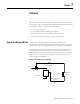
Preface Read this preface to familiarize yourself with the rest of the manual. This preface covers the following topics: Who should use this manual How to use this manual Related publications Conventions used in this manual Rockwell Automation support Who Should Use This Manual Use this manual if you are responsible for designing, installing, programming, or troubleshooting control systems that use the Allen-Bradley Compact I/O system.
2 Preface Related Documentation The table below provides a listing of publications that contain important information about MicroLogix 1500 systems. For Read this document Document number A user manual containing information on how to install, MicroLogix 1500 User Manual use and program your MicroLogix 1500 controller. 1764-UM001 A user manual containing information on how to install, DeviceNet Adapter User Manual and use your 1769-ADN DeviceNet adapter.
Chapter 1 Overview This chapter explains how analog data is used, describes the 1769-IF4I isolated analog input module, and describes the 1769-OF4CI and 1769-OF4VI isolated analog output modules. Included is information about: How to Use Analog I/O Data the use of analog I/O. the modules’ hardware and diagnostic features. an overview of the 1769 analog input system operation. an overview of the 1769 analog output system operation.
1-2 Overview General Description The 1769-IF4I isolated analog input module converts and digitally stores analog data for retrieval by controllers, such as the CompactLogix controller or the MicroLogix 1500 controller. The module supports connections from any combination of as many as four voltage or current analog sensors. The 1769-IF4I input module provides four, isolated-differential analog input channels.
Overview 1-3 Figure 1.2 Isolated Analog Modules’ Hardware Features 1 2a 3 OK Analog DANGER Do Not Remove RTB Under Power Unless Area is Non-Hazardous 10a Ch0+ N/C Ch0_iRtn N/C Ch0- Ch1+ N/C Ch1_iRtn Ch2+ 10 Ch1Ch2_iRtn N/C Ch2Ch3+ N/C Ch3_iRtn 10b N/C Ch3- 4 Ensure Adjacent Bus Lever is Unlatched/Latched Before/After Removing/Inserting Module 1769-IF4I 8a 7a 7a 2b OK Analog 5a 5b 9 6 7b 7b 8b Table 1.
1-4 Overview General Diagnostic Features The analog modules contain diagnostic features that can help you identify the source of problems that may occur when cycling power or during normal channel operation. These power cycle and channel diagnostics are explained in chapter 5. System Overview The modules communicate to the controller through the bus interface. The modules also receive 5 and 24V dc power through the bus interface. You can install as many analog modules as your power supply can support.
Overview 1-5 System Operation When you cycle power, the module performs a check of its internal circuits, memory, and basic functions. During this time, the module status OK LED remains off. If no faults are found during power-cycle diagnostics, the module status OK LED is turned on. After power-cycle checks are complete, the module waits for valid channel configuration data. If an invalid configuration is detected, the module generates a configuration error.
1-6 Overview Module Operation The following sections describe the input and output modules’ block diagrams. Input Module Block Diagram The input module’s input circuitry consists of four isolated-differential analog inputs each with it’s own analog-to-digital (A/D) converter. The A/D converter reads the selected input signal and converts it to a digital value that is presented to the controller. Figure 1.
Overview 1-7 Output Modules Block Diagram The output modules use one digital-to-analog (D/A) converter per isolated output channel to convert the digital output data from the controller to an analog output signal. Figure 1.
1-8 Overview Figure 1.6 1769-OF4VI Block Diagram LED OPTO DAC + _ Vout0+ OPTO Vout00 DC / DC Converter 0 BUS ASIC CPU OPTO DAC + _ Vout3+ OPTO Vout33 DC / DC Converter 3 Module Field Calibration Each isolated analog modules’s calibration is guaranteed by its design. No field calibration is required.
Chapter 2 Installation and Wiring This chapter tells you how to: Compliance to European Union Directives determine the power requirements for the modules. avoid electrostatic damage. install the module. wire the module’s terminal block. wire input devices. wire output devices. This product is approved for installation within the European Union and EEA regions. It has been designed and tested to meet the following directives.
2-2 Installation and Wiring Industrial Automation, Wiring and Grounding Guidelines for Noise Immunity, publication 1770-4.1 Automation Systems Catalog, publication B113 Power Requirements The modules receive power through the bus interface from the +5V dc/+24V dc system power supply. Table 2.
Installation and Wiring 2-3 Hazardous Location Considerations This equipment is suitable for use in Class I, Division 2, Groups A, B, C, D or non-hazardous locations only. The following attention statement applies to use in hazardous locations. ATTENTION EXPLOSION HAZARD Substitution of components may impair suitability for Class I, Division 2. Do not replace components or disconnect equipment unless power has been switched off or the area is known to be non-hazardous.
2-4 Installation and Wiring Remove Power ATTENTION Remove power before removing or inserting this module. When you remove or insert a module with power applied, an electrical arc may occur. An electrical arc can cause personal injury or property damage by: sending an erroneous signal to your system’s field devices, causing unintended machine motion. causing an explosion in a hazardous environment.
2-5 Installation and Wiring For mounting instructions, see Panel Mounting Using the Dimensional Template on page 2-7, or DIN-rail Mount on page 2-8. To work with a system that is already mounted, see Replace a Single Module Within a System on page 2-8. Figure 2.1 Assemble the Compact I/O System 3 4 2 1 6 1 5 1. Disconnect power. 2. Check that the bus lever of the module to be installed is in the unlocked (fully right) position. 3.
2-6 Installation and Wiring 6. To allow communication between the controller and module, move the bus lever fully to the left (4) until it clicks. Ensure it is locked firmly in place. ATTENTION When attaching I/O modules, it is very important that the bus connectors are securely locked together to be sure of proper electrical connection. 7. Attach an end cap terminator (5) to the last module in the system by using the tongue-and-groove slots as before. 8. Lock the end cap bus terminator (6).
Installation and Wiring 2-7 Panel Mount Mount the module to a panel using two screws per module. Use M4 or #8 panhead screws. Mounting screws are required on every module. Figure 2.3 Panel Mounting Using the Dimensional Template Overall hole spacing tolerance: ±0.4 mm (0.016 in.). Locate holes every 17.5 mm (0.689 in.) to allow for a mix of single-wide and one-and-a-half-wide modules (for example, the 1769-OA16 module). Host Controller Spacing for single-wide modules 35 mm (1.378 in.).
2-8 Installation and Wiring DIN-rail Mount The module can be mounted using the following DIN rails: 35 x 7.5 mm (EN 50 022 - 35 x 7.5) or 35 x 15 mm (EN 50 022 - 35 x 15). Before mounting the module on a DIN rail, close the DIN rail latches. Press the DIN rail mounting area of the module against the DIN rail. The latches will momentarily open and lock into place. Replace a Single Module Within a System The module can be replaced while the system is mounted to a panel (or DIN rail).
Installation and Wiring 2-9 6. Before installing the replacement module, be sure that the bus lever on the module to be installed and on the right-side adjacent module are in the unlocked (fully right) position. 7. Slide the replacement module into the open slot. 8. Connect the modules together by locking (fully left) the bus levers on the replacement module and the right-side adjacent module. 9. Replace the mounting screws (or snap the module onto the DIN rail).
2-10 Installation and Wiring System Wiring Guidelines Consider the following when wiring your system. General Guidelines Channels are isolated from each other. Do not use the analog module’s NC terminals as connection points. To ensure optimum accuracy, limit overall cable impedance by keeping your cable as short as possible. Locate the I/O system as close to your sensors or actuators as your application will permit. Use Belden 8761, or equivalent, shielded wire.
Installation and Wiring 2-11 1769-IF4I Input Module Guidelines If multiple power supplies are used with analog inputs, the power supply commons must be kept at potentials that do not result in the module’s working voltage rating being exceeded. The 1769-IF4I module does not provide loop power for analog inputs. Use power supplies that match the input transmitter specifications. Differential analog inputs are more immune to noise than single-ended analog inputs.
2-12 Installation and Wiring Where: Rc = DC resistance of the cable (each conductor) depending on cable length Rs = Source impedance of analog transducer/sensor input Ri = Impedance of the voltage input (1 M for 1769-IF4I) Vs = Voltage source (voltage at the transducer/sensor input device) Vin = Measured potential at the module input %Ai = Percent added inaccuracy in a voltage-based system due to source and cable impedance.
Installation and Wiring 2-13 Effect of Device and Cable Output Impedance on Output Module Accuracy The maximum value of the output impedance is shown in the example below, because it creates the largest deviation from an ideal voltage source. Figure 2.
2-14 Installation and Wiring Vin % Ai = 1 – --------- 100 Publication 1769-UM014B-EN-P - May 2010 Vs
Installation and Wiring 2-15 As output impedance (Rs) and/or resistance (dc) of the cable (Rc) get larger, system accuracy decreases. If you determine that the inaccuracy error is significant, implementing the following equation in the control program can compensate for the added inaccuracy error due to the impedance of the output module and cable.
2-16 Installation and Wiring Remove the Finger-safe Terminal Block When wiring field devices to the module, it is not necessary to remove the terminal block. If you remove the terminal block, use the write-on label on the side of the terminal block to identify the module slot location and type. RTB position can be indicated by circling either the R for right side or L for left side. Figure 2.
Installation and Wiring 2-17 4. Tighten the terminal screw making sure the pressure plate secures the wire. Recommended torque when tightening terminal screws is 0.68 Nm (6 lb-in). TIP If you need to remove the finger-safe cover, insert a screwdriver into one of the square, wiring holes and gently pry the cover off. If you wire the terminal block with the finger-safe cover removed, you will not be able to put it back on the terminal block because the wires will be in the way.
2-18 Installation and Wiring Figure 2.8 Belden 8761 Wire Cut foil shield and drain wire. Cable Signal Wire Signal Wire Drain Wire Foil Shield Signal Wire Signal Wire To wire your module follow these steps. 1. At each end of the cable, strip some casing to expose the individual wires. 2. Trim the signal wires to 2-inch lengths. Strip about 5 mm (3/16 in.) of insulation away to expose the end of the wire. ATTENTION Be careful when stripping wires.
Installation and Wiring 2-19 Analog Input Module Wiring Figure 2.9 1769-IF4I Terminal Layout W ARNING -Do Not Remove TB R Unless Area is Non-Hazar Ch0+ N/C Ch0_iRtn N/C N/C Ch0+ Ch0_iRtn Ch0- N/C N/C Ch1+ Ch1+ Ch0- Ch1_iRtn N/C Ch1_iRtn Ch2+ Ch1Ch2_iRtn N/C Ch2Ch3+ N/C Ch3_iRtn N/C Ch3- Ch2+ Ch1Ch2_iRtn N/C Ch2Ch3+ N/C Ch3_iRtn N/C Ch3- 1769-IF4I Figure 2.
2-20 Installation and Wiring Figure 2.11 1769-IF4I Wiring Single-ended Sensor/Transmitter Types Sensor/ + Transmitter Supply (1) Current Transmitter + Signal Voltage Transmitter Ground + Signal Voltage Transmitter + Ground Signal Figure 2.
Installation and Wiring 2-21 Analog Output Modules Wiring Figure 2.13 1769-OF4CI Terminal Layout DANGER Do Not Remove RTB Under Powe Unless Area is Non-Hazardous N/C N/C N/C N/C I out 0- I out 0+ N/C I out 0I out 0+ N/C N/C N/C I out 1I out 1+ N/C I out 1I out 1+ N/C N/C N/C I out 2I out 2+ N/C I out 2I out 2+ N/C N/C N/C I out 3- I out 3I out 3+ I out 3+ N/C N/C +24V N/C dc N/C Ensure Adjacent Bus Lever Unlatched/Latched Before/ Removing/Inserting Module 1769-OF4CI Figure 2.
2-22 Installation and Wiring Figure 2.15 1769-OF4VI Terminal Layout DANGER Do Not Remove RTB Under Powe Unless Area is Non-Hazardous N/C N/C N/C V out 0- V out 0+ N/C V out 0+ N/C N/C V out 0N/C N/C V out 1V out 1+ N/C V out 1+ N/C V out 1N/C N/C V out 2V out 2+ N/C V out 2+ N/C N/C V out 3- V out 3+ V out 2N/C V out 3- V out 3+ N/C N/C +24V N/C dc N/C Ensure Adjacent Bus Lever Unlatched/Latched Before/ Removing/Inserting Module 1769-OF4VI Figure 2.
Chapter 3 Module Data, Status, and Channel Configuration for the Input Module This chapter examines the analog input module’s data table, channel status, and channel configuration word. 1769-IF4I Input Module Addressing The1769-IF4I memory map shows the output, input, and configuration tables for the 1769-IF4I module. Figure 3.
3-2 Module Data, Status, and Channel Configuration for the Input Module 1769-IF4I Input Image The 1769-IF4I input image file represents data words and status bits. Input words 0 to 3 hold the input data that represents the value of the analog inputs for channels 0 to 3. These data words are valid only when the channel is enabled and there are no errors. Input words 5 and 6 hold the status bits. To receive valid status information, the channel must be enabled.
3-3 Module Data, Status, and Channel Configuration for the Input Module The input data table lets you access analog input module read data for use in the control program, via word and bit access. The data table structure is shown in the table below. For each input module, slot x, words 0 to 3 in the input data file contain the analog values of the inputs. Table 3.
3-4 Module Data, Status, and Channel Configuration for the Input Module High Alarm Flag Bits (H0 to H3) Word 6, bits 2, 6, 10, 14 contain the high alarm flag bits for input channels 0 to 3 and applies to all input types. If set (1), the input signal is outside the user-defined range. The module continues to convert analog data to maximum full-range values. The bit is automatically reset (0) when the high alarm condition clears, unless the channel’s alarm bits are latched.
Module Data, Status, and Channel Configuration for the Input Module 1769-IF4I Output Data File 3-5 The output data table lets you access analog output module write data for use in the control program, via word and bit access. Table 3.2 1769-IF4I Output Data Table Word Bit Position 15 14 13 12 11 10 0 Nu(1) Nu Nu Nu Nu Nu Nu Nu UL3(2) UH3(3) UL2 UH2 UL1 UH1 UL0 UH0 9 8 7 6 5 4 3 2 1 0 (1) Nu = Not used. Bit must be set to 0. (2) ULx = Unlatch Low Process Alarm Latch x.
3-6 Module Data, Status, and Channel Configuration for the Input Module 1769-IF4I Configuration Data File The configuration file lets you determine how each individual input channel will operate. Parameters such as the input type and data format are set up using this file. This data file is writable and readable. The default value of the configuration data table is all zeros. Word Table 3.
3-7 Module Data, Status, and Channel Configuration for the Input Module Channel Configuration Each channel’s configuration words consist of bit fields, the settings of which determine how the channel operates. See the table below and the descriptions that follow for valid configuration settings and their meanings. The default bit status of the configuration file is all zeros. Table 3.4 Bit Definitions for Channel Configuration Words Define To Select Input Filter 60 Hz Selection 50 Hz 28.
3-8 Module Data, Status, and Channel Configuration for the Input Module Enable/Disable Channel This configuration selection lets each channel to be individually enabled. TIP When a channel is not enabled (0), no voltage or current input is provided to the controller by the A/D converter. Input Filter Selection The input filter selection field lets you select the filter frequency for each channel and provides system status of the input filter setting for analog input channels 0 to 3.
Module Data, Status, and Channel Configuration for the Input Module 3-9 Module Update Time and Scanning Process The module update time is defined as the time required for the module to sample and convert the input signals of all enabled input channels and provide the resulting data values to the controller. For the 1769-IF4I, each input channel is continuously sampled at an independent rate determined by the filter setting selected for each channel.
3-10 Module Data, Status, and Channel Configuration for the Input Module Input Data Selection Formats This selection configures channels 0 to 3 to present analog data in any of the following formats. Raw/Proportional Data Engineering Units Scaled-for-PID Percent Range Raw/Proportional Data The value presented to the controller is proportional to the selected input and scaled into the maximum data range allowed by the bit resolution of the A/D converter and filter selected.
Module Data, Status, and Channel Configuration for the Input Module 3-11 Valid Input Data Word Formats/Ranges The following table shows the valid formats and min./max. data ranges provided by the module. Table 3.7 Valid Input Data 1769-IF4I Normal Operating Input Range Full Range (includes amounts over and under normal operating range) Raw/Proportional Data -10…+10V dc +10.5…-10.5V -32767… +32767 0…5V dc -0.5…5.25V 0…10V dc -0.5…10.5V 4…20 mA 3.2…21 mA 1.0…5V dc 0.5…5.
3-12 Module Data, Status, and Channel Configuration for the Input Module The module compares the Real Time Sample Rate value entered in Word 0 of the Configuration Data file with each input channel’s calculated update time, again based on the filter setting selected for each enabled channel. If the value entered for the Real Time Sample Rate is smaller than any input channel’s calculated update time, the module indicates a configuration error.
Module Data, Status, and Channel Configuration for the Input Module 3-13 1769-IF4I Process Alarms Process alarms alert you when the module has exceeded configured high or low limits for each channel. You can latch process alarms. Process alarms can generate interrupts. (CompactLogix L43 controllers will be able to support these interrupts.
3-14 Module Data, Status, and Channel Configuration for the Input Module Figure 3.2 Alarm Deadbands High High alarm turns ON. High alarm turns OFF. Normal Input Range Low alarms turns ON. Low Low alarms turns OFF. Alarm Deadbands 43153 The value entered for a channel’s alarm deadband value must be within the normal operating data range as set by the Input Data Format selected for that channel.
Chapter 4 Module Data, Status, and Channel Configuration for the Output Modules This chapter examines the analog output module’s output data file, input data file, channel status, and channel configuration words. 1769-OF4CI Output Module Memory Map The 1769-OF4CI memory map shows the output, input, and configuration tables for the 1769-OF4CI module. Figure 4.
4-2 Module Data, Status, and Channel Configuration for the Output Modules 1769-OF4VI Output Module Memory Map The 1769-OF4VI memory map shows the output, input, and configuration tables for the 1769-OF4VI module. Figure 4.
Module Data, Status, and Channel Configuration for the Output Modules 1769-OF4CI and -OF4VI Output Data File 4-3 The structure of the output data file is shown in the table below. Words 0 to 3 contain the commanded analog output data for channels 0 to 3, respectively. The most significant bit is the sign bit. Word 4 contains the control bits for unlatching alarms. Word Table 4.
4-4 Module Data, Status, and Channel Configuration for the Output Modules 1769-OF4CI and -OF4VI Input Data File This data table file provides immediate access to channel diagnostic information and analog output data at the module for use in the control program. To receive valid data, you must enable the channel. The data table structure is described below. Word Table 4.
Module Data, Status, and Channel Configuration for the Output Modules 4-5 1769-OF4CI and -OF4VI Under-Range Flag Bits (U0 to U3) Word 1, bits 1, 5, 9, and 13 contain the under-range bits for channels 0 to 3. When set (1), the under-range bit indicates that the controller is attempting to drive the analog output below its normal operating range or below the channel’s Low Clamp level (if clamp limits are set for the channel).
4-6 Module Data, Status, and Channel Configuration for the Output Modules 1769-OF4CI and -OF4VI Output Data Loopback/Echo Words 2 to 5 provide output loopback/data echo through the Input Data file for channels 0 to 3. The value of the data echo is the analog value currently being converted on-board the module by the D/A converter. This ensures that the logic-directed state of the output is true. Otherwise, the state of the output could vary depending on controller mode.
4-7 Module Data, Status, and Channel Configuration for the Output Modules 1769-OF4CI and -OF4VI Configuration Data File The configuration file lets you determine how each individual output channel will operate. Parameters such as the output type/range and data format are set up using this file. The configuration data file is writable and readable. The default value for the configuration data file is all zeros. The structure of the channel configuration file is explained below. Table 4.
4-8 Module Data, Status, and Channel Configuration for the Output Modules 1769-OF4CI and -OF4VI Channel Configuration The first two words of each eight word group in the configuration file allow you to change the parameters of each channel independently. For example, words 8 and 9 correspond to channel 1 while words 24 and 25 correspond to channel 3. Table 4.
4-9 Module Data, Status, and Channel Configuration for the Output Modules 1769-OF4CI Table 4.
4-10 Module Data, Status, and Channel Configuration for the Output Modules Clamping/Limiting Clamping limits the output from the analog module to remain within a range configured by the controller, even when the controller commands an output outside that range. This safety feature sets a high clamp and a low clamp.
Module Data, Status, and Channel Configuration for the Output Modules 4-11 Ramping Ramping limits the speed at which an analog output signal can change. This prevents fast transitions in the output from damaging the devices that an output module controls. Table 4.8 Ramping Types Ramping Type Description Ramp to Fault Mode This type of ramping occurs when the present output value changes to the Fault Value after a communications fault occurs.
4-12 Module Data, Status, and Channel Configuration for the Output Modules Table 4.10 1769-OF4VI Output Range/Types and Output Data Formats Output Data Format Output Range/Type Total Counts in Full Scale Number of Counts for Every 1% of Ramp Rate Real Units/Second for Every 1% of Ramp Rate 65534 655 0.2V/s Proportional Counts -10…+10V 0…5V 0.05V/s 0…10V 0.1V/s 1…5V 0.04V/s Engineering Units -10…+10V 21000 210 0.2V/s 0…5V 5750 58 0.05V/s 0…10V 11000 110 0.1V/s 1…5V 4750 48 0.
Module Data, Status, and Channel Configuration for the Output Modules 4-13 Hold for Initialization Hold for Initialization causes outputs to hold present state until the value commanded by the controller matches the value held by the module providing a bumpless transfer. If Hold for Initialization is selected, outputs hold if any of these three conditions occur.
4-14 Module Data, Status, and Channel Configuration for the Output Modules 1769-OF4CI and -OF4VI Program/Idle Mode (PM) This configuration selection provides individual program/idle mode selection for the analog channels. When this selection is disabled [the bit is reset (0)], the module holds the last state, meaning that the analog output remains at the last converted value prior to the condition that caused the control system to enter the Program mode.
Module Data, Status, and Channel Configuration for the Output Modules 4-15 1769-OF4CI and -OF4VI Fault Value Using words each channel’s Fault Value word, you can specify the values the outputs will assume when the system enters the fault mode. The default value is 0. Valid values are dependent upon the range selected in the range selection field. If the value you entered is outside the normal operating range for the output range selected, the module generates a configuration error.
4-16 Module Data, Status, and Channel Configuration for the Output Modules 1769-OF4CI and -OF4VI Program/Idle Value Use each channel’s Program/Idle Mode word to set the integer values for the outputs to assume when the system enters the program mode. The values are dependent upon the range selected in the range selection field. If the value you entered is outside the normal operating range for the output range selected, the module generates a configuration error. The default value is 0.
4-17 Module Data, Status, and Channel Configuration for the Output Modules 1769-OF4CI Valid Output Data Word Formats/Ranges The following table shows the valid formats and data ranges accepted by the module. Table 4.11 1769-OF4CI Valid Output Data Table Decimal Range Decimal Range Decimal Range Decimal Range 22000 21000 18431 17407 11250 10625 21.0 mA +21.0 mA +21.0 mA Over 32767 32767 21000 21000 17407 17407 10625 10625 4.0 mA to 20.0 mA +20.0 mA +20.
4-18 Module Data, Status, and Channel Configuration for the Output Modules 1769-OF4VI Valid Output Data Word Formats/Ranges The following table shows the valid formats and data ranges accepted by the module. Table 4.12 1769-OF4VI Valid Output Data Table Decimal Range Decimal Range Decimal Range Decimal Range 11000 10500 17202 16793 11000 10500 +10.5V dc +10.5V dc +10.5V dc Over 32767 32767 10500 10500 16793 16793 10500 10500 -10… +10V dc +10.0V dc +10.
4-19 Module Data, Status, and Channel Configuration for the Output Modules Table 4.12 1769-OF4VI Valid Output Data Table Decimal Range Decimal Range Decimal Range Decimal Range 11000 10500 18021 17202 11000 10500 +10.5V dc +10.5V dc +10.5V dc Over 32767 32767 10500 10500 17202 17202 10500 10500 0.0… 10.0V dc +10.0V dc +10.0V dc Normal 29788 29788 10000 10000 16383 16383 10000 10000 0.0V dc 0.0V dc Normal -29788 -29788 0 0 0 0 0 0 -0.5V dc -0.5V dc -0.
4-20 Module Data, Status, and Channel Configuration for the Output Modules Notes: Publication 1769-UM014B-EN-P - May 2010
Chapter 5 Module Diagnostics and Troubleshooting This chapter describes troubleshooting the analog input and output modules. This chapter contains information on: Safety Considerations safety considerations when troubleshooting. module versus channel operation. the module’s diagnostic features. critical vs. non-critical errors. module condition data. Safety considerations are an important element of proper troubleshooting procedures.
5-2 Module Diagnostics and Troubleshooting Stand Clear of the Machine When troubleshooting any system problem, have all personnel remain clear of the machine. The problem could be intermittent, and sudden unexpected machine motion could occur. Have someone ready to operate an emergency stop switch in case it becomes necessary to shut off power to the machine.
Module Diagnostics and Troubleshooting 5-3 Internal diagnostics are performed at both levels of operation. When detected, module error conditions are immediately indicated by the module status LED. Both module hardware and channel configuration error conditions are reported to the controller. Channel over-range or under-range conditions are reported in the module’s input data table. Module hardware errors are typically reported in the controller’s I/O status file.
5-4 Module Diagnostics and Troubleshooting Open-circuit Detection (1769-IF4I Module Only) The module performs an open-circuit test on all enabled channels configured for 4 to 20 mA inputs and for all voltage inputs. Whenever an open-circuit condition occurs, the under-range bit for that channel is set on all channels configured for 4 to 20 mA inputs or the over-range bit for that channel is set on all channels configured for voltage inputs in the Input Data file.
Module Diagnostics and Troubleshooting 5-5 Module Error Field The purpose of the module error field is to classify module errors into three distinct groups, as described in the table below. The type of error determines what kind of information exists in the extended error information field. These types of module errors are typically reported in the controller’s I/O status file. Refer to your controller manual for details. Table 5.
5-6 Module Diagnostics and Troubleshooting Configuration Errors If you set the fields in the configuration file to invalid or unsupported values, the module ignores the invalid configuration, generates a non-critical error, and keeps operating with the previous configuration. Each type of analog module has different features and different error codes. See 1769-IF4I Extended Error Codes on page 5-6 and 1769-OF4CI and -OF4VI Extended Error Codes on page 5-8.
Module Diagnostics and Troubleshooting 5-7 Table 5.
5-8 Module Diagnostics and Troubleshooting Table 5.
Module Diagnostics and Troubleshooting 5-9 Table 5.
5-10 Module Diagnostics and Troubleshooting Notes: Publication 1769-UM014B-EN-P - May 2010
Appendix A Specifications General Specifications for 1769-IF4I, -OF4CI, and -OF4VI Modules Table A.1 General Specifications Specification Value Dimensions (HxDxW) 118 mm x 87 mm x 35 mm (4.65 in. x 3.43 in. x 1.38 in.) Height including mounting tabs 138 mm (5.43 in.) Approximate Shipping Weight (with carton) 300 g (0.
A-2 Specifications Table A.1 General Specifications (cont.
Specifications 1769-IF4I Input Specifications A-3 Table A.2 1769-IF4I Specifications Specification 1769-IF4I Analog Normal Operating Voltage: ± 10V dc, 0…10V dc, 0…5V dc, 1…5V dc Current: 0…20 mA, 4…20 mA Ranges(1) Full Scale Analog Ranges(1) Voltage: ± 10.5V dc, 0…10.5V dc, 0…5.25V dc, 0.5…5.25V dc Current: 0…21 mA, 3.2…21 mA Number of Inputs 4 isolated differential Bus Current Draw, Max 145 mA at 5V dc 125 mA at 24V dc Heat Dissipation 3.
A-4 Specifications Table A.2 1769-IF4I Specifications (cont.) Specification 1769-IF4I Accuracy Drift with Temperature Voltage Terminal: ±0.003% per °C Current Terminal: ±0.0045% per °C Calibration The module performs only initial factory calibration. Non-linearity (in percent full scale) ±0.03% Repeatability(1) ±0.03% Voltage: ±0.3% Module Error over Full Temperature Range 0…+60 °C (+32…+140 °F) Current: ±0.
Specifications 1769-OF4CI Output Specifications A-5 Table A.3 1769-OF4CI Specifications Specification 1769-OF4CI Analog Normal Operating Ranges(1) 0…20 mA, 4…20 mA Full Scale Analog Ranges(1) 0…21 mA, 3.2…21 mA Number of Outputs 4 isolated differential Bus Current Draw, Max 145 mA at 5V dc 140 mA at 24V dc Heat Dissipation 2.68 total W (All points - 21 mA into 250 - worst case calculated.) Digital Resolution Across Full Range 16 bits (unipolar) +4…+20 mA: 15.59 bits, 0.
A-6 Specifications Table A.
Specifications 1769-OF4VI Output Specifications A-7 Table A.4 1769-OF4VI Specifications Specification 1769-OF4VI Analog Normal Operating Ranges(1) ± 10V dc, 0…10V dc, 0…5V dc, 1…5V dc Full Scale Analog Ranges(1) ± 10.5V dc, -0.5…10.5V dc, -0.5…5.25V dc, 0.5…5.25V dc Number of Outputs 4 isolated differential Bus Current Draw, Max 145 mA at 5V dc 75 mA at 24V dc Heat Dissipation 2.0 total W (All points - 10V dc into 2 k - worst case calculated.
A-8 Specifications Table A.4 1769-OF4VI Specifications Specification 1769-OF4VI Accuracy Drift with Temperature ±0.0086% FS per °C Output Ripple(1) Range 0…50 kHz (referred to output range) ±0.05% Non-linearity (in percent full scale) ±0.05% Repeatability(2) (in percent full scale) ±0.05% Output Error Over Full Temperature Range 0…60 °C (+32…+140 °F) ±0.
Appendix B Module Addressing and Configuration with MicroLogix 1500 This appendix examines the analog modules’ addressing scheme and describes module configuration using RSLogix 500 and MicroLogix 1500 software. Input Module Addressing In the following example, the 1769-IF4I module is used. Detailed information on the input image table can be found in 1769-IF4I Input Data File on page 3-3. Figure B.
B-2 Module Addressing and Configuration with MicroLogix 1500 Input Module’s Input Image The input modules’ input image file represents data words and status bits. Input words 0 to 3 hold the input data that represents the value of the analog inputs for channels 0 to 3. These data words are valid only when the channel is enabled and there are no errors. Input words 4 and 5 hold the status bits. To receive valid status information, the channel must be enabled.
Module Addressing and Configuration with MicroLogix 1500 B-3 Input Module’s Configuration File The configuration file contains information that you use to define the way a specific channel functions. The configuration file is explained in more detail in chapter 3. The configuration file is modified using the programming software configuration screen. For an example of module configuration using RSLogix 500 software, see Configure Analog I/O Modules in a MicroLogix 1500 System on page B-4.
B-4 Module Addressing and Configuration with MicroLogix 1500 Configure Analog I/O Modules in a MicroLogix 1500 System This example takes you through configuring your 1769 analog input and output modules with RSLogix 500 programming software.
Module Addressing and Configuration with MicroLogix 1500 B-5 Publication 1769-UM014B-EN-P - May 2010
B-6 Module Addressing and Configuration with MicroLogix 1500 Notes: Publication 1769-UM014B-EN-P - May 2010
Appendix C Configuration Using the RSLogix 5000 Generic Profile for CompactLogix Controllers To configure a 1769 analog I/O module for a CompactLogix controller in RSLogix 5000 software using the Generic Profile, you must first begin a new project in RSLogix 5000 software. 1. Click on the new project icon or on the FILE pull down menu and select NEW. The following screen appears. 2. Choose your controller type and enter a name for your project.
C-2 Configuration Using the RSLogix 5000 Generic Profile for CompactLogix Controllers 3. Click OK. The following main RSLogix 5000 screen appears. The last entry in the controller organizer on the left of the screen shown above is a line labeled [0] CompactBus Local. 4. Right click on this line, select New Module. The following screen appears.
Configuration Using the RSLogix 5000 Generic Profile for CompactLogix Controllers C-3 This screen narrows your search for I/O modules to configure into your system. 5. Click OK. The following default Generic Profile screen appears. This is the default Generic Profile screen. The first area to fill in for the Generic Profile screen is the name. This helps to easily identify the module type configured on your local Compact Bus.
C-4 Configuration Using the RSLogix 5000 Generic Profile for CompactLogix Controllers Use the following table for the Comm Format, Assembly Instance and Size values for the 1769-IF4I, -OF4CI, and -OF4VI modules if you have an earlier version of RSLogix 5000 software, version 15. 1769 I/O Modules Comm Format Parameter Assembly Instance Size (16-bit) IF4I Input Data – INT Input 101 7 Output 100 1 Config 102 26 Input 101 6 Output 100 5 Config 102 32 OF4CI and OF4VI Data – INT 8.
Configuration Using the RSLogix 5000 Generic Profile for CompactLogix Controllers C-5 9. Click OK to complete the configuration of your I/O module. You may choose to inhibit the module or have the controller fault if the connection to this I/O module fails. The defaults for these two parameters are not to inhibit the module and not to fault the controller should an I/O module connection fail.
C-6 Configuration Using the RSLogix 5000 Generic Profile for CompactLogix Controllers Configure I/O Modules Once you have created Generic Profiles for each analog I/O module in your system, you must then enter configuration information into the Tag database that has been automatically created from the Generic Profile information you entered for each of these modules. This configuration information is downloaded to each module at program download, going to run, and at power cycle.
Configuration Using the RSLogix 5000 Generic Profile for CompactLogix Controllers C-7 Tag addresses are automatically created for configured I/O modules. All local I/O addresses are preceded by the word Local. These addresses have the following format: Input Data: Local:s.I Output Data: Local:s.O Configuration Data: Local:s.C where s is the slot number assigned the I/O modules in the Generic Profiles.
C-8 Configuration Using the RSLogix 5000 Generic Profile for CompactLogix Controllers Notes: Publication 1769-UM014B-EN-P - May 2010
Appendix D Configure Modules in a Remote DeviceNet System with a 1769-ADN DeviceNet Adapter Overview In this example, the 1769-IF4I and 1769-OF4CI modules are in a remote DeviceNet system controlled by a 1769-ADN DeviceNet adapter. RSNetWorx for DeviceNet software, version 2.23 or later, is used to configure the network and the I/O modules. The configuration method described here must be done prior to configuring the DeviceNet adapter in the DeviceNet scanner’s scanlist.
D-2 Configure Modules in a Remote DeviceNet System with a 1769-ADN DeviceNet Adapter Add the DeviceNet Adapter to the Scanlist In this part of the example, the 1769-ADN adapter is added to the DeviceNet scanner’s scanlist. 1. Start the RSNetWorx for DeviceNet software. 2. In the left column under Category, click the + sign next to Communication Adapters. 3. In the list of products, double-click the 1769-ADN to place it on the network.
Configure Modules in a Remote DeviceNet System with a 1769-ADN DeviceNet Adapter D-3 4. To configure I/O for the adapter, double-click the adapter icon that appears on the network. 5. Click the Module Configuration tab. TIP The I/O Summary tab provides the configured sized and format of the I/O data. The Transaction tab lets you send services supported by the device. The Clear/Reset Memory transaction returns the module’s configuration to the factory defaults, that is, empty.
D-4 Configure Modules in a Remote DeviceNet System with a 1769-ADN DeviceNet Adapter Configure the 1769-IF4I Input Module Example The 1769-ADN adapter appears in slot 0. Your I/O modules, power supplies, end caps, and interconnect cables must be entered in the proper order, following the 1769 I/O rules contained in the DeviceNet Adapter User Manual, publication 1769-UM001. To simplify this example, we placed the 1769-IF4I in slot 1 to show how it is configured. 1.
Configure Modules in a Remote DeviceNet System with a 1769-ADN DeviceNet Adapter D-5 3. Double-click on 1769-IF4I. 4. Under the General tab, select the appropriate bank. Bank 1 was selected in this example.
D-6 Configure Modules in a Remote DeviceNet System with a 1769-ADN DeviceNet Adapter 5. Under the Configuration Settings tab, you can select the parameter that you want to configure and initiate an action using the toolbar. By default, the 1769-IF4I module contains six input words and no output words. 6. Click the Data Description button to see what the six input words represent.
Configure Modules in a Remote DeviceNet System with a 1769-ADN DeviceNet Adapter D-7 If you are using external 24V dc power for your 1769-IF4I module, you must click the white box to the left of Using External +24v Power Source, so that a check mark appears in the box. Do not click on the box if you are not using external 24V dc power. Each of the four analog input channels are disabled by default. To enable a channel, click its Enable box, so that a check mark appears in it.
D-8 Configure Modules in a Remote DeviceNet System with a 1769-ADN DeviceNet Adapter 1769-IF4I External Power Example In this example, channels 0 through 4 are used and external power is being supplied from an external 24V dc power source. In addition, channels 0 and 1 are driven by 4 to 20 mA transducers, while channels 2 and 3 are driven by devices generating 0 to 10V dc analog signals. Throughput is not a concern for this application. However, noise immunity is.
Configure Modules in a Remote DeviceNet System with a 1769-ADN DeviceNet Adapter Configure the 1769-OF4CI Output Module Example D-9 After leaving the 1769-IF4I configuration screen, the I/O Bank 1 screen for the 1769-ADN adapter should look like the following: 1. Click on the pull-down arrow next to the empty slot and this time choose the 1769-OF4CI module. 2. Click on the Slot 2 button that appears to the right of the 1769-OF4CI module.
D-10 Configure Modules in a Remote DeviceNet System with a 1769-ADN DeviceNet Adapter 3. Click on the Configuration Settings button to see what the eleven input and nine output words represent. The eleven input words contain channel diagnostic data for the eight channels. The nine output words contain the actual analog output data for the eight channels along with one additional word containing the control bits for unlatching alarms. 4.
Configure Modules in a Remote DeviceNet System with a 1769-ADN DeviceNet Adapter D-11 1769-OF4CI Output Channels Example Each of the two analog output channels are disabled by default. To enabled a channel, click its Enable box so that a check mark appears in it. Then, choose your Output Range, Data Format, and the state or your outputs should the controlling controller be placed into the program mode, fault, or lose communications.
D-12 Configure Modules in a Remote DeviceNet System with a 1769-ADN DeviceNet Adapter Therefore, a value of 6241 (decimal) must be used in the event the controlling controller is placed into Program/Fault mode, faults, or loses communications. The decimal number 6241 represents 4 mA, when using the Raw/Proportional Data Format. Click OK, and your configuration for the 1769-OF4CI analog output module is complete.
Appendix E Two’s Complement Binary Numbers The controller memory stores 16-bit binary numbers. Two’s complement binary is used when performing mathematical calculations internal to the controller. Analog input values from the analog modules are returned to the controller in 16-bit two’s complement binary format. For positive numbers, the binary notation and two’s complement binary notation are identical.
E-2 Two’s Complement Binary Numbers Negative Decimal Values In two’s complement notation, the far left position is always 1 for negative values. The equivalent decimal value of the binary number is obtained by subtracting the value of the far left position, 32768, from the sum of the values of the other positions. In Figure E.2 all positions are 1 and the value is 32767 32768 = -1. Figure E.
Glossary The following terms and abbreviations are used throughout this manual. For definitions of terms not listed here refer to the Allen-Bradley Industrial Automation Glossary, publication AG-7.1. A/D converter– Refers to the analog to digital converter inherent to the module. The converter produces a digital value whose magnitude is proportional to the magnitude of an analog input signal.
2 configuration word – Contains the channel configuration information needed by the module to configure and operate each channel. D/A Converter– Refers to the digital to analog converter inherent to the output module. The converter produces an analog dc voltage or current signal whose instantaneous magnitude is proportional to the magnitude of a digital value. dB – (decibel) A logarithmic measure of the ratio of two signal levels.
3 LSB – (Least Significant Bit) The bit that represents the smallest value within a string of bits. For analog modules, 16-bit, two’s complement binary codes are used in the I/O image in the card. For analog inputs, the LSB is defined as the rightmost bit, bit 0, of the 16-bit field. For analog outputs, the three rightmost bits are not significant, and the LSB is defined as the third bit from the right, bit 2, of the 16-bit field.
4 ideal over the full input range is the overall accuracy. this is expressed in percent of full scale. Gain error, offset error, and linearity error all contribute to input and output channel accuracy. output accuracy – The difference between the actual analog output value and what is expected, when a given digital code is applied to the d/a converter. Expressed as a ± percent of full scale.
Index Numerics 1769-ADN configuration example D-1 user manual Preface-2 A A/D converter 1-6 definition 1-1 abbreviations 1-1 alarm deadband 3-13 process 3-13 analog input module data 3-3 definition 1-1 overview 1-1 attenuation definition 1-1 B bus connector definition 1-1 locking 2-6 bus interface 1-4 C calibration 1-8 channel definition 1-1 diagnostics 5-3 status LED 1-5 step response 3-8 channel update time definition 1-1 CMRR.
2 Index F fault condition at power-up 1-5 fault value 4-15 filter 3-8 definition 1-2 filter frequency 3-8 and channel step response 3-8 definition 1-2 finger-safe terminal block 2-15 frequency cut-off frequency 3-9 FSR. See full scale range. full scale definition 1-2 full scale error definition 1-2 full scale range definition 1-2 G gain error. See full scale error.
Index output module channel configuration 4-8 configuration data file 4-7 enable channel 4-9 output module status general status bits 4-4 hold last state bits 4-5 over-range flag bits 4-4 under-range flag bits 4-5 overall accuracy definition 1-4 over-range flag bits 3-4, 4-4 P panel mounting 2-7 positive decimal values E-1 power-up diagnostics 5-3 power-up sequence 1-5 process alarms 1769-IF8 modules 3-13 program alteration 5-2 program/idle mode 4-13, 4-14 program/idle to fault enable 4-14 program/idle va
4 Index Notes: Publication 1769-UM014B-EN-P - May 2010
Rockwell Automation Support Rockwell Automation provides technical information on the Web to assist you in using its products. At http://www.rockwellautomation.com/support/, you can find technical manuals, a knowledge base of FAQs, technical and application notes, sample code and links to software service packs, and a MySupport feature that you can customize to make the best use of these tools.