Compact I/O Analog Output Module Catalog Number 1769-OF4 User Manual
Important User Information Solid state equipment has operational characteristics differing from those of electromechanical equipment. Safety Guidelines for the Application, Installation and Maintenance of Solid State Controls (publication SGI-1.1 available from your local Rockwell Automation sales office or online at http://www.rockwellautomation.com/literature/) describes some important differences between solid state equipment and hard-wired electromechanical devices.
Table of Contents Preface Introduction . . . . . . . . . . . . . . . . About This Publication . . . . . . . . Who Should Use This Publication Additional Resources. . . . . . . . . . . . . . . . . . . . . . . . . . . . . . . . . . . . . . . . . . . . . . . . . . . . . . . . . . . . . . . . . . . . . . . . . . . . . . . . . . . . . . . . . . . . . . 7 7 7 8 . . . . . . . . . . . . . . . . . . . . . . . . . . . . . . . . . . . . . . . . . . . . . . . . . . . . . . . . . . .
Table of Contents Under-range (low clamp) Status Bits (U0…U3) . . . . . . Output Data File . . . . . . . . . . . . . . . . . . . . . . . . . . . . . . . Cancel Clamp Alarm Latch Control Bits (CLO0…CLO3 and CHO0…CHO3) . . . . . . . . . . . . . . . . . . . . . . . . . . Configuration Data File . . . . . . . . . . . . . . . . . . . . . . . . . . Channel Configuration . . . . . . . . . . . . . . . . . . . . . . . . . . Enable/Disable Channel (EC) . . . . . . . . . . . . . . . . . . . Program Mode (PM). . . . .
Table of Contents Appendix A Specifications Introduction . . . . . . . . . . . . . . . . . General Specifications – 1769-OF4 . Output Specifications – 1769-OF4 . Certifications – 1769-OF4. . . . . . . . Replacement Parts. . . . . . . . . . . . . . . . . . . . . . . . . . . . . . . . . . . . . . . . . . . . . . . . . . . . . . . . . . . . . . . . . . . . . . . . . . . . . . . . . . . . . . . . . . . . . . . . . . . . . . . . . . . . 51 51 52 53 53 Introduction . . . . . . . . . . . . .
Table of Contents 6 Publication 1769-UM020A-EN-P - December 2009
Preface Introduction Read this preface to familiarize yourself with the rest of the manual. Topic About This Publication Page About This Publication 7 Who Should Use This Publication 7 Additional Resources 8 This manual is a guide for using the Compact I/O Analog Output Module, catalog number 1769-OF4. It describes the procedures you use to configure, operate, and troubleshoot your module.
Preface Additional Resources These documents contain additional information about control systems that use Compact I/O modules. Resource Description MicroLogix 1500 User Manual, publication 1764-UM001 A user manual containing information on how to install, use, and program your MicroLogix 1500 controller. DeviceNet Adapter User Manual, publication 1769-UM001 A user manual containing information on how to install and use your 1769-ADN DeviceNet adapter.
Chapter 1 Overview Introduction Topic Module Description Page Module Description 9 System Overview 11 Module Operation 11 The module converts digital data from controllers to provide analog output data. The module provides the following output types and ranges. Normal and Full Ranges Signal Type Voltage Current Normal Operating Input Range Full Module Range ±10V DC ± 10.5V DC 1…5V DC 0.5…5.25V DC 0…5V DC -0.5…5.25V DC 0…10V DC -0.5…10.5V DC 0…20 mA 0…21 mA 4…20 mA 3.
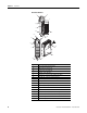
Chapter 1 Overview Hardware Features 1 2a 3 OK Analog DANGER Do Not Remove RTB Under Power Unless Area is Non-Hazardous 10a V out 0 + I out 0+ V out 1+ I out 1+ V out 2+ 10 I out 2+ V out 3+ I out 3 + ANLG Com ANLG Com 10b Ensure Adjacent Bus Lever is Unlatched/Latched Before/After Removing/Inserting Module 4 1769-OF4 8a 7a 7a 2b OK Analog 5a 5b 9 6 7b 10 7b 8b Item Description 1 Bus lever (with locking function) 2a Upper-panel mounting tab 2b Lower-panel mounting tab 3 Mod
Overview System Overview Chapter 1 The module communicates to the controller through the bus interface. The module also receives 5 and 24V DC power through the bus interface. You can install as many analog modules as your power supply can support. However, the modules may not be located more than eight modules away from the system power supply.
Chapter 1 Overview The channel status words are described in the Input Data File on page 31. The controller uses two’s complement binary data when communicating with the module. This typically occurs at the end of the program scan or when commanded by the control program. If the controller and the module determine that the bus data transfer was made without error, the input data is used in your control program and the output data is used by the module. No field calibration is required.
Chapter 2 Installation and Wiring Introduction Topic General Considerations Page General Considerations 13 Assemble the Compact I/O System 16 Mounting the Module 17 Replace a Single Module Within a System 19 Grounding the Module 20 System Wiring Guidelines 21 Label the Terminals 23 Remove the Finger-safe Terminal Block 23 Wire the Finger-safe Terminal Block 24 Wire the Modules 25 The Compact I/O system is suitable for use in an industrial environment when installed in accordance wi
Chapter 2 Installation and Wiring Hazardous Location Considerations This equipment is suitable for use in Class I, Division 2, Groups A, B, C, D or nonhazardous locations only. The following attention statement applies to use in hazardous locations. ATTENTION EXPLOSION HAZARD • Substitution of components may impair suitability for Class I, Division 2. • Do not replace components or disconnect equipment unless power has been switched off or the area is known to be nonhazardous.
Installation and Wiring Chapter 2 Removing Power ATTENTION Remove power before removing or inserting this module. When you remove or insert a module with power applied, an electrical arc may occur. An electrical arc can cause personal injury or property damage by: • sending an erroneous signal to your system’s field devices, causing unintended machine motion. • causing an explosion in a hazardous environment.
Chapter 2 Installation and Wiring Assemble the Compact I/O System The module can be attached to the controller or an adjacent I/O module before or after mounting. For mounting instructions, see Panel Mounting By Using the Dimensional Template on page 18, or Mount to a DIN Rail on page 19. To work with a system that is already mounted, see Replace a Single Module Within a System on page 19. 3 4 2 1 6 1 5 1. Disconnect power. 2.
Installation and Wiring Chapter 2 6. To allow communication between the controller and module, move the bus lever fully to the left (4) until it clicks. Make sure it is locked firmly in place. ATTENTION When attaching I/O modules, it is very important that the bus connectors are securely locked together to be sure of proper electrical connection. 7. Attach an end cap terminator (5) to the last module in the system by using the tongue-and-groove slots as before. 8. Lock the end cap bus terminator (6).
Chapter 2 Installation and Wiring Mount to a Panel Mount the module to a panel by using two screws per module. Use M4 or #8 panhead screws. Mounting screws are required on every module. Panel Mounting By Using the Dimensional Template Locate holes every 17.5 mm (0.689 in.) to allow for a mix of single-wide and one-and-a-half-wide modules (for example, the 1769-OA16 module). Host Controller 122.6 mm (4.826 in.) Overall hole spacing tolerance: ±0.4 mm (0.016 in.). 132 mm (5.197 in.
Installation and Wiring Chapter 2 6. Attach the modules to the panel by using the mounting screws. TIP If mounting more modules, mount only the last one of this group and put the others aside. This reduces remounting time during drilling and tapping of the next group. 7. Repeat steps 1…6 for any remaining modules. Mount to a DIN Rail The module can be mounted by using the following DIN rails: • 35 x 7.5 mm (EN 50 022 - 35 x 7.
Chapter 2 Installation and Wiring 4. On the right-side adjacent module, move its bus lever to the right (unlock) to disconnect it from the module to be removed. 5. Gently slide the disconnected module forward. If you feel excessive resistance, check that the module has been disconnected from the bus, and that both mounting screws have been removed or DIN latches opened.
Installation and Wiring System Wiring Guidelines Chapter 2 Consider the following when wiring your system: • All module commons (ANLG Com) are connected in the analog module. • The analog common (ANLG Com) is not connected to earth ground inside the module. • Channels are not isolated from each other. • For optimum accuracy, limit overall cable impedance by keeping your cable as short as possible. Locate the I/O system as close to your sensors or actuators as your application will permit.
Chapter 2 Installation and Wiring Effect of Transducer/Sensor and Cable Length Impedance on Voltage Output Accuracy For voltage outputs, the length of the cable used between the load and the module can affect the accuracy of the data provided by the module.
Installation and Wiring Chapter 2 As output impedance (Rs) and/or resistance (DC) of the cable (Rc) get larger, system accuracy decreases. If you determine that the inaccuracy error is significant, implementing the following equation in the control program can compensate for the added inaccuracy error due to the impedance of the module’s voltage outputs and cable.
Chapter 2 Installation and Wiring Wire the Finger-safe Terminal Block Upper Retaining Screw Lower Retaining Screw When wiring the terminal block, keep the finger-safe cover in place. 1. Loosen the terminal screws to be wired. 2. Begin wiring at the bottom of the terminal block and move up. 3. Route the wire under the terminal pressure plate. You can use the bare wire or a spade lug. The terminals accept a 6.35 mm (0.25 in.) spade lug. TIP The terminal screws are non-captive.
Installation and Wiring Chapter 2 Wire Size and Terminal Screw Torque Each terminal accepts up to two wires. Wire Type Wire Size Terminal Screw Torque Retaining Screw Torque Solid Cu-90 °C (194 °F) 0.325…2.080 mm2 (22…14 AWG) 0.68 N•m (6 lb•in) 0.46 N•m (4.1 lb•in) Stranded Cu-90 °C (194 °F) 0.325…1.310 mm2 (22…16 AWG) 0.68 N•m (6 lb•in) 0.46 N•m (4.1 lb•in) Wire the Modules ATTENTION To prevent shock hazard, care should be taken when wiring the module to analog signal loads.
Chapter 2 Installation and Wiring 3. Strip about 5 mm (3/16 in.) of insulation away to expose the end of the wire. ATTENTION Be careful when stripping wires. Wire fragments that fall into a module could cause damage when you cycle power. 4. At one end of the cable, twist the drain wire and foil shield together. Under normal conditions, this drain wire and shield junction must be connected to earth ground, via a panel or DIN rail mounting screw at the analog I/O module end.
Installation and Wiring Chapter 2 Wiring Analog Outputs Terminal Block V out 3+ I out 3+ V out 2+ I out 2+ Voltage Load Earth Ground ANLG Com ANLG Com V out 0+ I out 0+ V out 1+ I out 1 + Current Load Earth Ground ATTENTION Publication 1769-UM020A-EN-P - December 2009 Analog outputs may fluctuate for less than a second when power is applied or removed. This characteristic is common to most analog outputs.
Chapter 2 Installation and Wiring Notes: 28 Publication 1769-UM020A-EN-P - December 2009
Chapter 3 Module Data, Status, and Channel Configuration Introduction Topic Module Addressing Page Module Addressing 29 Input Data File 31 Output Data File 32 Configuration Data File 33 Channel Configuration 34 This memory map shows the output, input, and configuration tables for the module.
Chapter 3 Module Data, Status, and Channel Configuration Input Image The input image file represents data words and status bits. Word 0 holds the general status bits for each output channel as well as the over-range and under-range output-clamp status bits. To receive valid status information, the output channel must be enabled. Words 1…4 contain the data echo values for the most recent data sent to the output channels.
Module Data, Status, and Channel Configuration Input Data File Chapter 3 The input data file lets you access analog module read data for use in the control program, via word and bit access. The data table structure is shown in the table below. For each output module, slot x, word 0 contains the output-channel status bits. Words 1…4 in the intput data file contain the output channel data echo values. The most significant bit (MSB) is the sign bit, which is in two’s complement format.
Chapter 3 Module Data, Status, and Channel Configuration Under-range (low clamp) Status Bits (U0…U3) Under-range (low clamp) bits for output channels 0…3 are contained in Word 0, bits 9, 11, 13, and 15. When set (1), these bits indicate an output value sent to the module is less than or equal to the user-configured low clamp value for the output channel. The module clamps the analog output signal at the low clamp value.
Module Data, Status, and Channel Configuration Configuration Data File Chapter 3 The configuration file lets you determine how each individual output channel will operate. Parameters such as the output type and data format are set up by using this file. This data file is writable and readable. The default value of the configuration data table is all zeros.
Chapter 3 Module Data, Status, and Channel Configuration Channel Configuration Each channel is independently configured via a group of eight consecutive words in the Configuration Data file. The first two words of the group consist of bit fields, the settings of which determine how the output channel operates. See the tables below and the descriptions that follow for valid configuration settings and their meanings. The default bit status of the configuration file is all zeros.
Module Data, Status, and Channel Configuration Chapter 3 Enable/Disable Channel (EC) This configuration lets each channel be enabled individually. When a channel is not enabled (EC = 0), the output channel is set to 0V or 0 mA. Program Mode (PM) This configuration selection provides individual Program mode selection for the output channels. When this selection is disabled (PM = 0), the module holds the last state.
Chapter 3 Module Data, Status, and Channel Configuration Fault Mode (FM) This configuration selection provides individual Fault mode selection for the output channels. When this selection is disabled (FM = 0), the module holds the last state, meaning that the output remains at the last converted value prior to the condition that caused the control system to enter the Fault mode. IMPORTANT Hold last state is the default condition for the module during a control system Run-to-Fault mode change.
Module Data, Status, and Channel Configuration Chapter 3 Clamping (limiting) Clamping limits the outputs from the module to within a user-configured range when the controller commands an output to a value outside of that range. The module supports a high clamp value and a low clamp value for each output channel.
Chapter 3 Module Data, Status, and Channel Configuration Output Ramping Ramping limits the speed at which an output signal can change. This prevents vast transitions in the output from damaging the output controls. Ramp to Fault mode is the only type of ramping supported by the module. This type of ramping occurs when the present output value changes to the fault value after a change in the controller's status to Fault mode has occurred.
Module Data, Status, and Channel Configuration Chapter 3 This table describes how the ramp rate is determined for all output types/ranges and output data formats. Ramp Rates for Output Type/Range and Data Formats Output Data Format Proportional Counts Engineering Units Scaled for PID Percent of Full Scale Output Type/Range Total Counts in Full Scale Number of Counts for Every 1% of Ramp Rate Real Units/Second for Every 1% of Ramp Rate -10…10V DC 0.21V/s 0…5V DC 0.
Chapter 3 Module Data, Status, and Channel Configuration The ramp rate values are entered in the Configuration Data file and are accepted as valid only if: • the number of counts entered for a channel’s ramp rate is between a minimum of 1% and a maximum of 100% of the total number of full scale counts for the channel’s selected data format. • the number of counts entered for a channel’s ramp rate is equal to zero and ramping is not enabled for that channel.
Module Data, Status, and Channel Configuration Chapter 3 Engineering Units The value sent by the controller to the output channel is the actual current or voltage value for the selected output range. The resolution of the engineering units is 0.001V or 0.001 mA per count. Scaled-for-PID The value sent by the controller to the output channel is a signed integer with 0 representing the lower limit of the normal operating range and 16,383 representing the upper limit of the normal operating range.
Chapter 3 Module Data, Status, and Channel Configuration Notes: 42 Publication 1769-UM020A-EN-P - December 2009
Chapter 4 Module Diagnostics and Troubleshooting Introduction Topic Safety Considerations Page Safety Considerations 43 Power Cycle Diagnostics 45 Channel Diagnostics 45 Non-critical versus Critical Module Errors 45 Module Error Definition Table 46 Error Codes 47 Module Inhibit Function 50 Contacting Rockwell Automation 50 Safety considerations are an important element of proper troubleshooting procedures.
Chapter 4 Module Diagnostics and Troubleshooting Activate Devices When Troubleshooting When troubleshooting, never reach into the machine to actuate a device. Unexpected machine motion could occur. Stand Clear of the Machine When troubleshooting any system problem, have all personnel remain clear of the machine. The problem could be intermittent, and sudden unexpected machine motion could occur.
Module Diagnostics and Troubleshooting Power Cycle Diagnostics Channel Diagnostics Chapter 4 When you cycle power to the module, a series of internal diagnostic tests are performed. These diagnostic tests must be successfully completed or the module status indicator remains off and a module error results and is reported to the controller. Module Status Indicator Condition Corrective Action On Proper Operation No action required. Off Module Fault Cycle power.
Chapter 4 Module Diagnostics and Troubleshooting Module Error Definition Table Module errors are expressed in two fields as four-digit Hex format with the most significant digit as don’t care and irrelevant. The two fields are Module Error and Extended Error Information.
Module Diagnostics and Troubleshooting Error Codes Chapter 4 Error codes can help troubleshoot your module.
Chapter 4 Module Diagnostics and Troubleshooting Extended Error Codes for Configuration Errors Module Error Code Extended Error Information Code Binary Binary X40D 010 0 0000 1101 Invalid program/idle value (channel 0) X40E 010 0 0000 1110 Invalid program/idle value (channel 1) X40F 010 0 0000 1111 Invalid program/idle value (channel 2) X410 010 0 0001 0000 Invalid program/idle value (channel 3) X411 010 0 0001 0001 Invalid clamp value (channel 0) X412 010 0 0001 0010 Invalid cl
Module Diagnostics and Troubleshooting Chapter 4 Invalid Fault Value Selected(1) These error codes occur when the value entered is not within the full-range limits of the indicated channel, as determined by the channel’s output range/type and format setting, or the value entered is not within the limits set by the indicated channel’s output clamp values.
Chapter 4 Module Diagnostics and Troubleshooting Module Inhibit Function CompactLogix controllers support the module inhibit function. See your controller manual for details. Whenever the module is inhibited, it continues to provide information about changes at its inputs to the 1769 Compact Bus Master (for example, a CompactLogix controller).
Appendix A Specifications Introduction Topic General Specifications – 1769-OF4 Page General Specifications – 1769-OF4 51 Output Specifications – 1769-OF4 52 Certifications – 1769-OF4 53 Replacement Parts 53 Attribute 1769-OF4 Dimensions (HxWxD), approx. 118 x 35 x 87 mm (4.65 x 1.38 x 3.43 in.) Height including mounting tabs is 138 mm (5.43 in.) Shipping weight (with carton), approx. 280 g (0.
Appendix A Specifications Output Specifications – 1769-OF4 Attribute 1769-OF4 Vendor I.D. code 1 Product type code 10 Product code 48 Input words 5 Output words 5 Configuration words 32 Attribute Analog normal operating ranges(1) 1769-OF4 0…20 mA, 4…20 mA, ±10V DC, 0…10V DC, 0…5V DC, 1…5V DC Full scale analog ranges(1) 0…21 mA, 3.2…21 mA, ±10.5V DC, -0.5…10.5V DC, -0.5… 5.25V DC, 0.5… 5.
Specifications Appendix A Certifications – 1769-OF4 Certification Agency certification 1769-OF4 • C-UL certified (under CSA C22.2 No. 142) • UL 508 listed • CE compliant for all applicable directives Replacement Parts Hazardous environment class Class I, Division 2, Hazardous Location, Groups A, B, C, D (UL 1604, C-UL under CSA C22.2 No.
Appendix A Specifications Notes: 54 Publication 1769-UM020A-EN-P - December 2009
Appendix B Module Addressing and Configuration with MicroLogix 1500 Controller Introduction Topic Page Module Input Image 55 Module Configuration File 56 Configure Analog I/O Modules in a MicroLogix 1500 System 57 This appendix examines the modules’ addressing scheme and describes module configuration using RSLogix 500 software and a MicroLogix 1500 controller. Module Input Image The module’s input image file represents status bits and data echo words.
Appendix B Module Addressing and Configuration with MicroLogix 1500 Controller Module Output Image The module’s output image file represents data words and unlatch control bits. Output words 0…3 are written with output data that represents the analog value commanded to the module’s output channels 0…3. These data words only represent the state of the module’s outputs when the channel is enabled and there are no errors.
Module Addressing and Configuration with MicroLogix 1500 Controller Appendix B Software Configuration Channel Defaults Configure Analog I/O Modules in a MicroLogix 1500 System Parameter Default Setting Enable/Disable Channel Disabled Input/Output Range -10…10V DC Data Format Raw/Proportional This example takes you through configuring your 1769-OF4 module with RSLogix 500 programming software.
Appendix B Module Addressing and Configuration with MicroLogix 1500 Controller 4. Double-click I/O Configuration in the project tree to open the I/O Configuration dialog box. 5. On the I/O Configuration dialog box, select the slot position where you want to add your module. 6. In the Current Cards Available list, double-click Other – Requires I/O Card Type ID to add the module to the project in the indicated slot position.
Module Addressing and Configuration with MicroLogix 1500 Controller Appendix B 7. Enter the module identification parameters as shown. 8. Configure the module's channels by double-clicking the newly-added module and then clicking the Generic Extra Data Config tab. 9. Change the Radix to Hex/BCD. 10. Enter each of the 32 Configuration Data File words (in hexidecimal format) as required. See Configuration Data File on page 33 for details on setting up the configuration data. 11.
Appendix B Module Addressing and Configuration with MicroLogix 1500 Controller Notes: 60 Publication 1769-UM020A-EN-P - December 2009
Appendix C Configuration Using the RSLogix 5000 Generic Profile for CompactLogix Controllers Introduction Topic Page Add the Module to Your Project 61 Configure Each I/O Module 64 If the Add-on Profile for the 1769-OF4 module is not yet available, follow this procedure to configure your module by using a generic profile. Add the Module to Your Project 1. Start RSLogix 5000 software. 2. From the File menu, choose New to open an existing project or start a new project. 3.
Appendix C Configuration Using the RSLogix 5000 Generic Profile for CompactLogix Controllers 4. In the controller organizer, right-click CompactBus Local, and choose New Module. 5. Expand the Other group and select the 1769-MODULE Generic Profile. 6. Click OK.
Configuration Using the RSLogix 5000 Generic Profile for CompactLogix Controllers Appendix C 7. Type a Name for the module and an optional Description. 8. Select the slot number. The slot number begins with the first available slot number, 1, and increments automatically for each subsequent Generic Profile you configure. 9. Enter the Comm Format, Assembly Instance numbers and their associated sizes, as shown above. 10. Click OK. 11.
Appendix C Configuration Using the RSLogix 5000 Generic Profile for CompactLogix Controllers Configure Each I/O Module Once you have created Generic Profiles for each analog I/O module in your system, you must then enter configuration information into the Tag database that has been automatically created from the Generic Profile information you entered for each of these modules. This configuration information is downloaded to each module at program download, at going to run, and at power cycle.
Appendix D Two’s Complement Binary Numbers The controller memory stores 16-bit binary numbers. Two’s complement binary is used when performing mathematical calculations internal to the controller. Analog input values from the analog modules are returned to the controller in 16-bit two’s complement binary format. For positive numbers, the binary notation and two’s complement binary notation are identical.
Appendix D Two’s Complement Binary Numbers Negative Decimal Values In two’s complement notation, the leftmost position is always 1 for negative values. The equivalent decimal value of the binary number is obtained by subtracting the value of the leftmost position, 32,768, from the sum of the values of the other positions. All positions are 1 and the value is 32,767 - 32,768 = -1.
Glossary The following terms and abbreviations are used throughout this manual. For definitions of terms not listed here refer to the Allen-Bradley Industrial Automation Glossary, publication AG-7.1. alternate last state – A configuration selection that instructs the module to convert a user-specified value from the channel fault or program/idle word to the output value when the module enters the Fault or Program mode. attenuation – The reduction in the magnitude of a signal as it passes through a system.
Glossary full scale range – (FSR) The difference between the maximum and minimum specified analog input values. hold last state – A configuration selection that instructs the module to keep the outputs at the last converted value prior to the condition that caused the control system to enter the Fault or Program mode. input image – The input from the module to the controller. The input image contains the module data words and status bits.
Glossary overall accuracy – The worst-case deviation of the output voltage or current from the ideal over the full output range is the overall accuracy. Gain error, offset error, and linearity error all contribute to output channel accuracy. output accuracy – The difference between the actual analog output value and what is expected, when a given digital code is applied to the d/a converter. Expressed as a ± percent of full scale.
Glossary Notes: 70 Publication 1769-UM020A-EN-P - December 2009
Index Numerics 1769-ADN user manual 8 A abbreviations 67 alternate last state definition 67 attenuation definition 67 B bus connector definition 67 locking 17 bus interface 11 C channel definition 67 diagnostics 45 status indicator 11 clamp high data value word 37 clamp low data value word 37 clamping 37 configuration errors 47 configuration word definition 67 contacting Rockwell Automation 50 D D/A converter definition 67 data echo definition 67 data word definition 67 dB definition 67 decibel. See dB.
Index installation 13-20 grounding 20 heat and noise considerations 15 L latch clamp status selection 37 least significant bit. See LSB. LED. See status indicators.
Index Notes: Publication 1769-UM020A-EN-P - December 2009 73
Index Notes: 74 Publication 1769-UM020A-EN-P - December 2009
Rockwell Automation Support Rockwell Automation provides technical information on the Web to assist you in using its products. At http://www.rockwellautomation.com/support/, you can find technical manuals, a knowledge base of FAQs, technical and application notes, sample code and links to software service packs, and a MySupport feature that you can customize to make the best use of these tools.