Installation Instructions Compact™ Solid State 24V dc Source, High Current Output Module (Catalog Number 1769-OB8, Series A) Inside Module Description ................................................................................. 3 Environment and Enclosure ..................................................................... 4 System Assembly..................................................................................... 5 Mounting Compact I/O Modules ............................................
Compact™ Solid State 24V dc Source, High Current Output Module Important User Information Because of the variety of uses for the products described in this publication, those responsible for the application and use of these products must satisfy themselves that all necessary steps have been taken to assure that each application and use meets all performance and safety requirements, including any applicable laws, regulations, codes and standards.
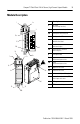
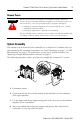
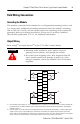
Compact™ Solid State 24V dc Source, High Current Output Module 3 Module Description 1 Item Description 2a 3 D ANGER Do Not R emo ve R TB Under P ower Unless Area is Non-Hazardous 10a OUT 0 OUT 2 +VDC 1 OUT 1 1 bus lever (with locking function) 2a upper panel mounting tab 2b lower panel mounting tab 3 I/O diagnostic LEDs 4 module door with terminal identification label 5a movable bus connector with female pins 5b stationary bus connector with male pins 6 nameplate label 7a upper ton
Compact™ Solid State 24V dc Source, High Current Output Module Environment and Enclosure ATTENTION ! This equipment is intended for use in a Pollution Degree 2 industrial environment, in overvoltage Category II applications (as defined in IEC publication 60664-1), at altitudes up to 2000 meters without derating. This equipment is considered Group 1, Class A industrial equipment according to IEC/CISPR Publication 11.
Compact™ Solid State 24V dc Source, High Current Output Module 5 Remove Power ATTENTION ! Remove power before removing or inserting this module. When you remove or insert a module with power applied, an electrical arc may occur.
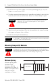
Compact™ Solid State 24V dc Source, High Current Output Module 5. Push the bus lever back slightly to clear the positioning tab (3). Use your fingers or a small screw driver. 6. To allow communication between the controller and module, move the bus lever fully to the left (4) until it clicks. Ensure it is locked firmly in place. ATTENTION ! When attaching I/O modules, it is very important that the bus connectors are securely locked together to ensure proper electrical connection. 7.
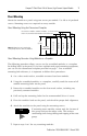
Compact™ Solid State 24V dc Source, High Current Output Module 7 Panel Mounting Mount the module to a panel using two screws per module. Use M4 or #8 panhead screws. Mounting screws are required on every module. Panel Mounting Using the Dimensional Template End Cap Compact I/O 122.6±0.2 (4.826±0.008) 28.5 (1.12) 35 (1.38) Compact I/O Note: All dimensions are in mm (inches). Hole spacing tolerance: ±0.4 mm (0.016 in.). Compact I/O 132 (5.
Compact™ Solid State 24V dc Source, High Current Output Module DIN Rail Mounting The module can be mounted using the following DIN rails: 35 x 7.5 mm (EN 50 022 - 35 x 7.5) or 35 x 15 mm (EN 50 022 - 35 x 15). Before mounting the module on a DIN rail, close the DIN rail latches. Press the DIN rail mounting area of the module against the DIN rail. The latches will momentarily open and lock into place.
Compact™ Solid State 24V dc Source, High Current Output Module 9 Field Wiring Connections Grounding the Module This product is intended to be mounted to a well-grounded mounting surface such as a metal panel. Additional grounding connections from the module’s mounting tabs or DIN rail (if used), are not required unless the mounting surface cannot be grounded. Refer to Industrial Automation Wiring and Grounding Guidelines, Allen-Bradley publication 1770-4.1, for additional information.
Compact™ Solid State 24V dc Source, High Current Output Module A removable, write-on label is provided with the module. Remove the label from the door, mark the identification of each terminal with permanent ink, and slide the label back into the door. Your markings (ID tag) will be visible when the module door is closed. SLOT # _____ MODULE TYPE ______ Removing the Finger-Safe Terminal Block When wiring field devices to the module, it is not necessary to remove the terminal block.
Compact™ Solid State 24V dc Source, High Current Output Module 11 2. Route the wire under the terminal pressure plate. You can use the bare wire or a spade lug. The terminals will accept a 6.35 mm (0.25 in.) spade lug. TIP The terminal screws are non-captive. Therefore, it is possible to use a ring lug [maximum 1/4 inch o.d. with a 0.139 inch minimum i.d. (M3.5)} with the module. 3. Tighten the terminal screw making sure the pressure plate secures the wire.
Compact™ Solid State 24V dc Source, High Current Output Module I/O Memory Mapping Output Data File For each module, slot x, word 0 in the output data file contains the control program’s directed state of the discrete output points.
Compact™ Solid State 24V dc Source, High Current Output Module 13 1769-OB8 Configuration File The read/writable configuration data file allows the setup of the hold last state and user-defined safe state conditions. The manipulation of the bits from this file is normally done with programming software (e.g. RSLogix 500, RSNetWorx for DeviceNet, etc.) during initial configuration of the system. In that case, graphical screens are provided via the programmer to simplify configuration.
Compact™ Solid State 24V dc Source, High Current Output Module Fault State, Word 3 Selects the hold last state or user-defined safe state condition for each individual output on a system transition from Run to Fault. Condition Bit Setting User-defined Safe State 0 Hold Last State 1 Fault Value, Word 4 Value Defines the fault state value (0=Off, 1=On). Each output is individually configurable for on or off.
Compact™ Solid State 24V dc Source, High Current Output Module 15 Specifications General Specifications Specification Value Dimensions 118 mm (height) x 87 mm (depth) x 35 mm (width) height including mounting tabs is 138 mm 4.65 in. (height) x 3.43 in (depth) x 1.38 in (width) height including mounting tabs is 5.43 in. Approximate Shipping Weight (with carton) 280g (0.61 lbs.
Compact™ Solid State 24V dc Source, High Current Output Module Output Specifications Specification 1769-OB8 Voltage Category 24V dc Operating Voltage Range 20.4V dc to 26.4V dc (source(1)) Number of Outputs 8 Bus Current Draw (maximum) 145 mA at 5V dc (0.725W) Heat Dissipation 2.20 Total Watts (Watts per point, plus minimum Watts, with all points energized.) Signal Delay (maximum) – resistive load turn-on =0.1 ms turn-off =1.0 ms at 60°C maximum load 2A, minimum V in 20.4V 1.
Compact™ Solid State 24V dc Source, High Current Output Module 17 Transistor Output Transient Pulses The maximum duration of the transient pulse occurs when minimum load is connected to the output. However, for most applications, the energy of the transient pulse is not sufficient to energize the load. ATTENTION ! A transient pulse occurs in transistor outputs when the external DC supply voltage is applied to the output common terminals (e.g. via the master control relay).
Compact™ Solid State 24V dc Source, High Current Output Module Hazardous Location Considerations This equipment is suitable for use in Class I, Division 2, Groups A, B, C, D or non-hazardous locations only. The following WARNING statement applies to use in hazardous locations. WARNING ! EXPLOSION HAZARD · Substitution of components may impair suitability for Class I, Division 2.
Compact™ Solid State 24V dc Source, High Current Output Module 19 For More Information For Refer to this Document Pub. No. A more detailed description of how to install MicroLogix 1200 & 1500 and use your Compact™ I/O with Programmable Controllers User MicroLogix™ 1200 & 1500 programmable Manual controller. 1764-UM001 A more detailed description of how to install 1769-ADN DeviceNet Adapter User and use your Compact I/O with the Manual 1769-ADN DeviceNet Adapter.
Notes: Publication 1769-IN063A-EN-P - March 2003 PN 40071-152-01(1) © 2003 Rockwell International Corporation. Printed in the U.S.A.