
User Manual

16 Compact 32-point Solid-state 24V dc Source Output Module
Publication 1769-IN080A-EN-P - August 2006
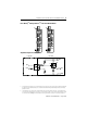
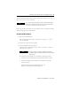
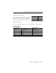
4. Insert the wire contact into the socket (3) (4).
Make sure that the tang (4) is properly latched by lightly pulling on the wire.
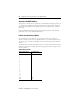
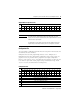
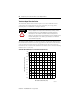
Output Data File
For each module, slot x, words 0…1 in the output data file contain the control
program’s directed state of the digital output points.
w = write
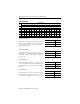
Output Module’s Input Data File
For each module, slot x, input data file words 0…1 contain the state of the
module’s output data (output data echo) file words 0…1. During normal operation,
these input bits represent the logic state that the outputs are directed to by the
control program. They are also dependent upon the:
• Program mode configuration (if supported by the controller).
• Fault mode configuration (if supported by the controller).
Output Data File
Word
Bit Position
15 14 13 12 11 10 9 8 7 6 5 4 3 2 1 0
0wwwwwwwwwwwwwwww
1wwwwwwwwwwwwwwww
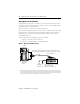
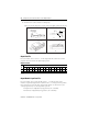
4 mm
(5/32 in)
4 mm
(5/32 in)
A
4 mm
(5/32 in)
4 mm
(5/32 in)
A
(1)
(2)
(3)
(4)
Tang
Wire
Stop