Installation Instructions Compact 32-point Solid-state 24V dc Source Output Module Catalog Number 1769-OB32T Topic Page About the 1769-OB32T Module 5 Spare/Replacement Module Parts 6 Install the 1769-OB32T Module 6 Replace a Single Module Within a System 7 Mount Expansion I/O 8 Mount Module to Panel 9 Mount Module to DIN Rail 10 Output Wiring 10 Wiring Options for the I/O Module 12 Ground the 1769-OB32T Module 14 Label for the 1492 Interface Module 14 Assemble the Wire Contacts 15
Compact 32-point Solid-state 24V dc Source Output Module Important User Information Solid state equipment has operational characteristics differing from those of electromechanical equipment. Safety Guidelines for the Application, Installation and Maintenance of Solid State Controls (publication SGI-1.1 available from your local Rockwell Automation sales office or online at http://literature.rockwellautomation.
Compact 32-point Solid-state 24V dc Source Output Module 3 Prevent Electrostatic Discharge ATTENTION Electrostatic discharge can damage integrated circuits or semiconductors if you touch bus connector pins. Follow these guidelines when you handle the module. – Touch a grounded object to discharge static potential. – Wear an approved wrist-strap grounding device. – Do not touch the bus connector or connector pins. – Do not touch circuit components inside the module.
Compact 32-point Solid-state 24V dc Source Output Module Hazardous Location Considerations This equipment is suitable for use in Class I, Division 2, Groups A, B, C, D or nonhazardous locations only. The following WARNING statement applies to use in hazardous locations. WARNING Explosion Hazard • Substitution of components may impair suitability for Class I, Division 2. • Do not replace components or disconnect equipment unless power is switched off or the area is known to be nonhazardous.
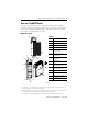
Compact 32-point Solid-state 24V dc Source Output Module 5 About the 1769-OB32T Module Compact I/O is suitable for use in an industrial environment when installed in accordance with these instructions. Specifically, this equipment is intended for use in clean, dry environments (Pollution degree 2(1)) and to circuits not exceeding Over Voltage Category II(2) (IEC 60664-1)(3).
Compact 32-point Solid-state 24V dc Source Output Module Spare/Replacement Module Parts You can order the 1746-N3 connector kit, which contains one connector and 40 terminals. Install the 1769-OB32T Module Attach the module to the controller or an adjacent I/O module before or after mounting. For mounting instructions, see Mount Module to Panel Using the Dimensional Template on page 9, or Mount Module to DIN Rail on page 10.
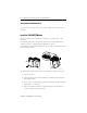
Compact 32-point Solid-state 24V dc Source Output Module 7 5. Use your fingers or a small screwdriver to push the bus lever back slightly to clear the positioning tab (3). 6. To allow communication between the controller and module, move the bus lever fully to the left (4) until it clicks, making sure it is locked firmly in place. ATTENTION When attaching I/O modules, it is very important that the bus connectors are securely locked together to be sure of proper electrical connection. 7.
Compact 32-point Solid-state 24V dc Source Output Module 6. Be sure that the bus lever on the module and on the right-side adjacent module are in the unlocked (fully-right) position before installing the replacement module. 7. Slide the replacement module into the open slot. 8. Connect the modules by locking (fully-left) the bus levers on the replacement module and the right-side adjacent module. 9. Replace the mounting screws (or snap the module onto the DIN rail).
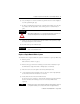
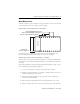
Compact 32-point Solid-state 24V dc Source Output Module 9 Mount Module to Panel Mount the module to a panel using two screws per module. Use M4 or #8 panhead screws. Mounting screws are required on every module. Mount Module to Panel Using the Dimensional Template Host Controller Spacing for Single-wide Modules 35 mm (1.378 in.) Spacing for One-and-a half-wide Modules 52.5 mm (2.067 in.) Refer to Host Controller Documentation for This Dimension. Overall hole spacing tolerance: ±0.4 mm (0.016 in.).
Compact 32-point Solid-state 24V dc Source Output Module 6. Attach the modules to the panel using the mounting screws. TIP If mounting more modules, mount only the last one of this group and put the others aside. This reduces the remounting time during drilling and tapping of the next group. 7. Repeat steps 1 to 6 for any remaining modules. Mount Module to DIN Rail The module can be mounted using these DIN rails. • 35 x 7.5 mm (EN 50 022 - 35 x 7.
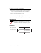
Compact 32-point Solid-state 24V dc Source Output Module 11 Basic Wiring(1) of Output Devices(2) to the 1769-OB32T Module +VDC 1 +VDC 2 +VDC 1 +VDC 2 24V dc 24V dc Simplified Output Circuit Diagram Logic Side User Side VDC S TR1 VCC ASIC G D OUT COM (1) Recommended Surge Suppression. Use a 1N4004 diode reverse-wired across the load for transistor outputs switching 24V dc inductive loads.
Compact 32-point Solid-state 24V dc Source Output Module Wiring Options for the I/O Module Included with your 32-point I/O module is a keyed 40-pin female connector and crimp-type pins. These components let you wire I/O devices to the module using a 40-conductor cable or individual wires. Refer to page 15 for connector/pin assembly instructions. When assembled, align the female connector over the module’s male header using the keying slot as a guide.
Compact 32-point Solid-state 24V dc Source Output Module 13 Option 2 - Use Allen-Bradley 1492 Wiring Systems 32-point I/O Module 1492-CABLExx (2)(3) Connects 32-point Module to DIN-rail Mountable Terminal Block Male MIL-C-83503 Header 8 mm (0.32 in.) REF. 0.2 to 4 mm2 (24 to 12 AWG) 1492-IFM40xx DIN-rail Mountable Terminal Block(1) 31562-M Allen-Bradley 1492 wiring systems are available for connecting 32-point I/O modules to external I/O.
Compact 32-point Solid-state 24V dc Source Output Module Ground the 1769-OB32T Module This product is intended to be mounted to a well-grounded mounting surface such as a metal panel. Additional grounding connections from the module’s mounting tabs or DIN rail (if used) are not required unless the mounting surface cannot be grounded. Refer to Industrial Automation Wiring and Grounding Guidelines, Allen-Bradley publication 1770-4.1, for additional information.
Compact 32-point Solid-state 24V dc Source Output Module 15 The 1492 interface module stick-on labels are abbreviated as follows: +V1 = V dc 1, +V2 = V dc 2, CM1 = Com 1, and so on. If you decide to build your cable using another 1746-N3 to terminate the cable at the 1492 interface-module end, wire it in the following manner: Pin 1 to Pin 1, Pin 2 to Pin 2, Pin 3 to Pin 3, and so on.
Compact 32-point Solid-state 24V dc Source Output Module 4. Insert the wire contact into the socket (3) (4). Make sure that the tang (4) is properly latched by lightly pulling on the wire. 4 mm (5/32 in) Tang 4 mm (5/32 in) Wire Stop (2) (1) A (3) (4) Output Data File For each module, slot x, words 0…1 in the output data file contain the control program’s directed state of the digital output points.
Compact 32-point Solid-state 24V dc Source Output Module 17 Output Module’s Input Data File Word Bit Position 15 14 13 12 11 10 9 8 7 6 5 4 3 2 1 0 0 r r r r r r r r r r r r r r r r 1 r r r r r r r r r r r r r r r r r = read The output module’s input data file reflects the output data echo of the module, not necessarily the electrical state of the output terminals. It does not reflect shorted or open outputs.
Compact 32-point Solid-state 24V dc Source Output Module Word Configuration File Bit Position 15 14 13 12 11 9 10 9 8 7 6 5 4 3 2 1 0 Fault Value for Output Array Word 1 10 0 0 0 0 0 0 0 0 0 0 0 0 0 0 0 0 11 0 0 0 0 0 0 0 0 0 0 0 0 0 0 0 0 12 0 0 0 0 0 0 0 0 0 0 0 0 0 0 0 0 13 0 0 0 0 0 0 0 0 0 0 0 0 0 0 0 0 14 0 0 0 0 0 0 0 0 0 0 0 0 0 0 0 0 15 0 0 0 0 0 0 0 0 0 0 0 0 0 0 0 0 Progra
Compact 32-point Solid-state 24V dc Source Output Module 19 Program to Fault Enable Bit (PFE) Word 0, bit 0, allows the selection of which data value, the program or fault value, to apply to the output if a system in Program mode undergoes a system fault, resulting a change to Fault mode. Value Applied Bit Setting Program 0 Fault 1 Module Default Condition The module’s default condition is all zeros, programming the conditions shown.
Compact 32-point Solid-state 24V dc Source Output Module Transistor Output Transient Pulses The maximum duration of the transient pulse occurs when minimum load is connected to the output. However, for most applications, the energy of the transient pulse is not sufficient to energize the load. A transient pulse occurs in transistor outputs when the external dc supply voltage is applied to the output common terminals (for example, via the master-control relay).
Compact 32-point Solid-state 24V dc Source Output Module 21 Specifications Compact 32-point Solid-state 24V dc Source Output Module - 1769-OB32T Attribute Value Voltage Category 24V dc Operating Voltage Range 10.2…26.4V dc (source)(3) Number of Outputs 32 Bus Current Draw, Max 220 mA @ 5V dc (1.10 W) Heat Dissipation 4.76 Total W (The W per point, plus the min W, with all points energized.) Signal Delay, Max – Resistive Load Turn-on = 0.5 ms Turn-off = 4.0 ms Off-state Leakage, Max(1) 0.
Compact 32-point Solid-state 24V dc Source Output Module (1) Typical Loading Resistor - To limit the effects of leakage current through solid state outputs, a loading resistor can be connected in parallel with your load. Use a 56 k ohm, 1/4 W resistor for this module’s outputs, 24V dc operation. (2) Recommended Surge Suppression - Use a 1N4004 diode reverse-wired across the load for transistor outputs switching 24V dc inductive loads.
Compact 32-point Solid-state 24V dc Source Output Module 23 Additional Resources You can view or download publications at http://literature.rockwellautomation.com. To order paper copies of technical documentation, contact your local Rockwell Automation distributor or sales representative. Related Documentation For Refer to This Document Pub. No.
Rockwell Automation Support Rockwell Automation provides technical information on the web to assist you in using its products. At http://support.rockwellautomation.com, you can find technical manuals, a knowledge base of FAQs, technical and application notes, sample code and links to software service packs, and a MySupport feature that you can customize to make the best use of these tools.