CompactLogix System Catalog Numbers 1769-L31, 1769-L32C, 1769-L32E, 1769-L35CR, 1769-L35E CompactLogix Controllers, POINT I/O Modules, PowerFlex 70 Drives, PowerFlex 40 Drives, PanelView Plus Terminals Quick Start
Important User Information Solid state equipment has operational characteristics differing from those of electromechanical equipment. Safety Guidelines for the Application, Installation and Maintenance of Solid State Controls (publication SGI-1.1 available from your local Rockwell Automation sales office or online at http://www.rockwellautomation.com/literature/) describes some important differences between solid state equipment and hard-wired electromechanical devices.
Where to Start Follow the path that matches your hardware and network configuration. Chapter 1 Prepare the CompactLogix Hardware Required page 17 Chapter 2 Prepare the Computer Required page 27 Optional Depending on your system. Chapter 3 Prepare the Distributed POINT I/O Hardware Chapter 4 Prepare the PowerFlex 70 Drive page 47 page 55 Optional Depending on your networks.
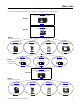
Where to Start How Hardware is Connected This quick start demonstrates the following possible control systems. Choose your hardware and networks, then follow the matching examples.
Where to Start Option 2: 1769-L32C, 1769-L35CR Control System 1769-L32C or 1769-L35CR with Optional 1769-SDN for the DeviceNet Network Computer with 1784-PCIC, -PCICS ControlNet Communication Card To Optional DeviceNet Network Serial (CP3 Cable) Distributed 1734 POINT I/O Modules with 1734-ACNR ControlNet Network with Taps PowerFlex 70 Drive with 20-COMM-C PowerFlex 40 Drive with 22-COMM-C PanelView Plus Terminal with ControlNet Communication Adapter Option 3: 1769-L31 Control System PanelView Plus
Where to Start Notes: 6 Publication IASIMP-QS001C-EN-P - October 2009
Table of Contents Preface Preface About This Publication . . . . . . . . . . . . . . . . . . . . . . . . . . . . . . . . . . . . . 11 Required Software . . . . . . . . . . . . . . . . . . . . . . . . . . . . . . . . . . . . . . . . . 12 Parts List . . . . . . . . . . . . . . . . . . . . . . . . . . . . . . . . . . . . . . . . . . . . . . . . . 13 Conventions . . . . . . . . . . . . . . . . . . . . . . . . . . . . . . . . . . . . . . . . . . . . . . 15 Additional Resources . . . . . . . . . . . . . . . . .
Table of Contents Mount the PowerFlex 70 Drive. . . . . . . . . . . . . . . . . . . . . . . . . . . . . . . 57 Wire Power . . . . . . . . . . . . . . . . . . . . . . . . . . . . . . . . . . . . . . . . . . . . . . . 57 Configure the Communication Adapter . . . . . . . . . . . . . . . . . . . . . . . . 58 Connect Communication Adapter to the PowerFlex 70 Drive . . . . . . 59 Additional Resources . . . . . . . . . . . . . . . . . . . . . . . . . . . . . . . . . . . . . . .
Table of Contents Chapter 9 Configure the DeviceNet Network Before You Begin. . . . . . . . . . . . . . . . . . . . . . . . . . . . . . . . . . . . . . . . . . 91 What You Need . . . . . . . . . . . . . . . . . . . . . . . . . . . . . . . . . . . . . . . . . . . 91 Follow These Steps . . . . . . . . . . . . . . . . . . . . . . . . . . . . . . . . . . . . . . . . 92 Apply Power to the DeviceNet Network . . . . . . . . . . . . . . . . . . . . . . . 93 Set the 1769-SDN Module’s Node Address . . . . . . . . .
Table of Contents Create DeviceNet Tags . . . . . . . . . . . . . . . . . . . . . . . . . . . . . . . . . . . . 154 Download the Project . . . . . . . . . . . . . . . . . . . . . . . . . . . . . . . . . . . . . 156 Schedule the ControlNet Network . . . . . . . . . . . . . . . . . . . . . . . . . . . 157 Test the PowerFlex 70 Tags . . . . . . . . . . . . . . . . . . . . . . . . . . . . . . . . 161 Test the PowerFlex 70 Tags . . . . . . . . . . . . . . . . . . . . . . . . . . . . . . . .
Preface About This Publication This quick start provides examples and procedures for the use of a CompactLogix system. This publication includes version 18 release updates for RSLogix 5000 programming software. The procedures cover many of the most common user tasks, such as: • connecting the controller to multiple devices (local and distributed I/O, drives, and a PanelView Plus terminal).
Required Software To complete examples in this quick start, you need one of the following software packages. If using network Use RSLogix 5000 programming software edition EtherNet/IP (Options 1, 2, and 3) •Full •Standard •Professional ControlNet (Option 2) •Standard DeviceNet (Option 3) •Standard •Professional •Professional If you do not use the RSLogix 5000 programming software packages recommended, you may need to purchase additional software to complete the examples in this quick start.
This table lists the hardware used in this quick start. The hardware you need depends on the options and examples you choose to complete. Specific hardware requirements are listed at the beginning of each chapter.
Quantity Catalog Number Description ControlNet Configuration 1 1769-L32CR CompactLogix ControlNet Controller with Redundant Tap 1 1784-PCIC or 1784-PCICS ControlNet Communication Card for a Personal Computer 1 1734-ACNR POINT I/O ControlNet Adapter 1 22-COMM-C ControlNet Adapter for Use With the PowerFlex 40 1 20-COMM-C ControlNet Adapter for Use With the PowerFlex 70 1 2711P-RN15S PanelView Plus 1000 ControlNet Interface Module 6 1786-TPR ControlNet Tap 2 1786-XT ControlNet Ter
This manual uses the following conventions. Conventions Convention Meaning Example bold Bold text denotes menus, menu items, buttons or options. Click OK. Check/uncheck Click to activate/deactivate a checkbox. Check the Do not show this dialog again checkbox. Click Click left mouse button once. (Assumes cursor is positioned on object or selection.) Click Browse. Courier font Type or enter text exactly as shown. Type cmd. Double-click Click left mouse button twice in quick succession.
Notes: 16 Publication IASIMP-QS001C-EN-P - October 2009
Chapter 1 Prepare the CompactLogix Hardware In this chapter, you install your CompactLogix hardware, including the controller, power supply, any local 1769 Compact I/O modules, and an optional 1769-SDN module (used only if you have distributed I/O on the DeviceNet network). Before You Begin Determine which of these networks and appropriate hardware to use: • For the EtherNet/IP network (option 1), use the 1769-L32E or 1769-L35E controller.
Chapter 1 Prepare the CompactLogix Hardware Follow These Steps Complete the steps shown for your controller.
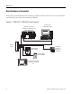
Prepare the CompactLogix Hardware Chapter 1 Connect the Battery to the Controller 1769-BA Battery 1. Insert the battery and battery connector. Battery Connector 2. Record the battery installation date in the box provided on the label. Battery Ethernet Address Box for Battery Installation Date Record the Ethernet Address (MAC) 1769-L32E or 1769-L35E controllers The Ethernet address (MAC) is found on a label near the battery. This is an example address.
Chapter 1 Prepare the CompactLogix Hardware Set the ControlNet Node Address 1769-L32C or 1769-L35CR controllers ControlNet Node Address Switches Controllers are shipped with the node address set at 99. Ones Tens 3 4 2 1 0 8 9 0 30 40 60 7 0 00 10 2 50 Tens Tens Digit 7 Ones 6 Ones Digit 5 1. Use a small, flathead screwdriver to set the node address to node 01. 80 90 01 Shown 2. Record the node address on the front panel overlay.
Prepare the CompactLogix Hardware Chapter 1 Assemble the System Controller, power supply, local I/O modules, 1769-SDN module, end cap terminator 1. On the top of each module, verify that all of the locking tabs are unlocked. Unlocked Locked 2. Use the tongue-and-groove slots to slide the power supply, then the I/O modules onto the controller. 3.
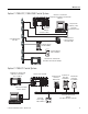
Chapter 1 Prepare the CompactLogix Hardware 5. Lock all of the locking tabs on the top of the modules. Locking Tab 6. Verify that the tabs are all the way to the left. 7. Slide the end cap terminator on and lock the locking tab. 8. Press the assembled system onto a DIN rail. End-cap Terminator Make Network Connections 1769-L32E or 1769-L35E controllers 1. Insert an Ethernet cable with an RJ-45 connector. 2. Connect the other end of the cable to an Ethernet switch.
Prepare the CompactLogix Hardware Chapter 1 1769-L32C or 1769-L35CR controllers Connect a ControlNet tap to port A of the controller. Port A A B A Port B (Do not use.) Required for all CompactLogix controllers 1. Connect the 1756-CP3 cable to the channel 0 serial port on the controller. 2. Connect the other end of the cable to a COM port on the computer.
Chapter 1 Prepare the CompactLogix Hardware 1769-SDN module 1. Connect a DeviceNet cable to the removable connector. Connect To Red V+ White CAN High Bare Shield Blue CAN Low Black V- 2. Connect the removable connector to the module.
Prepare the CompactLogix Hardware Chapter 1 Wire Power 1769-PA2 power supply WARNING Verify that all incoming power is turned off before wiring power. 1. Insert the 120/240V AC, V AC COM, and Chassis Ground wires and tighten the terminal screws. 2. Turn on incoming power.
Chapter 1 Prepare the CompactLogix Hardware Additional Resources Resource Description 1769-L32E and 1769-L35E CompactLogix Controller Installation Instructions, publication 1769-IN020 Provides details about assembling and mounting the controller and upgrading firmware as well as controller technical specifications. 1769-L32C and 1769-L35CR CompactLogix Controller Installation Instructions.
Chapter 2 Prepare the Computer In this chapter, you configure network communication on your computer and install the necessary programming and configuration software. Before You Begin • Verify that your computer meets the software’s system requirements for your edition of RSLogix 5000 programming software. • If using a ControlNet network (option 2), install a 1784-PCIC or 1784-PCICS ControlNet communication card on the computer. What You Need • RSLinx Classic software, version 2.
Chapter 2 Prepare the Computer Complete these steps. Terminology page 29 Install RSLogix Programming Software page 31 Configure a Serial Driver page 36 Set the IP Address for the Computer page 38 Configure the EtherNet/IP Driver in RSLinx page 40 Load Firmware page 42 Optional (Depending on your system.
Prepare the Computer Chapter 2 Terminology Ethernet networks use these types of addresses. Term Definition Ethernet Address Each Ethernet device has a unique Ethernet address (sometimes called a MAC address). The address appears as twelve digits separated by colons (for example, xx:xx:xx:xx:xx:xx). It is usually on a label on the device itself. Each digit is a number in hexadecimal (0 to 9 or A through F). No other device in the world will have the same address, and it can not be changed.
Chapter 2 Prepare the Computer ControlNet connection - 1769-L32C and 1769-L35CR controllers only Connect a ControlNet tap to port A of the ControlNet communication card in the computer. Computer with 1784-PCIC or 1784-PCICS communication card. ControlNet Tap on ControlNet Network Serial connection - Required for all controllers You connected a 1756-CP3 cable to a COM port on the computer and to the CH0 port on the controller in Chapter 1. 1756-CP3 serial cable to CH0 on 1769-L31.
Prepare the Computer Chapter 2 Install RSLogix Programming Software Required for all controllers Throughout the installation, click Next to use default RSLogix 5000 installation settings except when indicated in the steps below. 1. Begin the RSLogix 5000 software installation. 2. Choose your language and click Continue. 3. Accept the default software products for installation and click Next. 4. Enter your user name, organization, and software serial number, then click Next.
Chapter 2 Prepare the Computer 5. Accept the license agreement and click Next. 6. Click Next to install the program files to the default directory. 7. Select your activation type and click Next. This quick start uses FactoryTalk Activation software to activate RSLogix 5000 software. For more information, see the FactoryTalk Activation FAQ, publication Ftalk-FA017. 8. Click Next to install only the latest version of RSLogix 5000 software (version 18). 9.
Prepare the Computer Chapter 2 10. Click Next to install the typical firmware kits. 11. Click Next to install typical RSLogix Architect tools. 12. Click Next to install the typical set of EDS files and RSLinx software.
Chapter 2 Prepare the Computer 13. Click Install to complete the installation. The installation dialog box displays progress while the software installs. TIP As the installation progresses, you may be prompted to complete additional set-up tasks depending on your system configuration. Follow those prompts and enter information as indicated in the dialog boxes to complete your installation. After a few moments, the FactoryTalk Installation Wizard starts. 14. Click Next. 15.
Prepare the Computer Chapter 2 17. Select your host ID and click Next. The activation completes if the computer is connected to the Internet. If Internet access is not available, call Rockwell Automation Technical Support to complete your activation. 18. Click Finish to close the Activation Wizard.
Chapter 2 Prepare the Computer Configure a Serial Driver Required for all controllers 1. Launch RSLinx software. 2. Under Communications, select Configure Drivers. 3. Select RS-232 DF1 devices. 4. Click Add New. 5. Click OK to keep the default name.
Prepare the Computer Chapter 2 6. Select the Comm Port to which you connected the 1756-CP3 cable. 7. For Device, select Logix5550/CompactLogix. 8. Click Auto Configure. 9. Click OK. The Serial driver is added to the Configured Drivers list. 10. Verify that the Status of the driver is Running, and click Close. 11. Click the RSWho icon to view the driver. All of the configured, active drivers display. Expand the serial driver to see connected devices.
Chapter 2 Prepare the Computer Set the IP Address for the Computer Required for all controllers, regardless of network choice 1. On your desktop, right-click My Network Places and select Properties. 2. Double-click the Local Area Connection. 3. Click Properties. 4. On the General tab, select Internet Protocol (TCP/IP) and click Properties. 5. Select Use the following IP address and enter an IP address and Subnet mask for your computer using the example shown or enter your own address.
Prepare the Computer Chapter 2 9. Click the Support tab. 10. Verify that the IP Address and Subnet Mask match what you entered on the Network Worksheet. If these numbers do not match what you entered, contact your network administrator to verify that your IP address is correct. 11. Close the Local Area Connection Status dialog box.
Chapter 2 Prepare the Computer Configure the EtherNet/IP Driver in RSLinx Software Required for 1769-L32E,1767-L35E, and PanelView Plus 1. If RSLinx software is not open, launch RSLinx software. 2. From the Communications menu, choose Configure Drivers. 3. From the Available Driver Types, select Ethernet/IP Driver. 4. Click Add New. 5. Click OK to keep the default name. 6. Click OK to Browse Local Subnet.
Prepare the Computer Chapter 2 The EtherNet/IP driver is added to the Configured Drivers list. 7. Verify that the driver’s Status is Running, and click Close.
Chapter 2 Prepare the Computer Load Firmware Required for all packaged controllers TIP This example shows how to load firmware using a serial connection. It is faster to load firmware via an EtherNet/IP or ControlNet connection. For more information, see the installation instructions for the controller as listed at the end of the chapter. 1. Launch ControlFlash software. 2. Click Next. 3. Select the controller catalog number and click Next.
Prepare the Computer Chapter 2 4. Expand the AB_DF1-DFI driver, and select your controller. 5. Click OK. 6. Move the keyswitch on the controller to PROG. 7. If the Current Revision matches the revision of firmware you want, click Cancel and skip to Chapter 3. Otherwise, select the desired firmware revision and click Next. 8. Click Finish to start the firmware update.
Chapter 2 Prepare the Computer Install Additional Software • If you are completing the PanelView Plus chapters in this quick start, install FactoryTalkView Machine Edition software and RSLinx Enterprise software from the FactoryTalkView Machine Edition package. This software must be installed before you install any additional software. • If you are using a ControlNet network, install RSNetWorx for ControlNet software. • If you are using a DeviceNet network, install RSNetWorx for DeviceNet software.
Prepare the Computer Chapter 2 Additional Resources Resource Description 1769-L32E and 1769-L35E CompactLogix Controller Installation Instructions, publication Provides details about assembling and mounting the controller and upgrading firmware as well as controller technical specifications. 1769-L32C and 1769-L35CR CompactLogix Controller Installation Instructions.
Chapter 2 Prepare the Computer Notes: 46 Publication IASIMP-QS001C-EN-P - October 2009
Chapter 3 Prepare the Distributed POINT I/O Hardware In this chapter, you install the 1734 POINT I/O network adapter and the 1734 POINT I/O modules. Before You Begin • Determine which of these network adapters to use: – for an EtherNet/IP network (option 1), use the 1734-AENT adapter. – for a ControlNet network (option 2), use the 1734-ACNR adapter. – for a DeviceNet network (option 3), use the 1734-ADN adapter.
Chapter 3 Prepare the Distributed POINT I/O Hardware Follow These Steps If you have a POINT I/O system, complete these steps.
Prepare the Distributed POINT I/O Hardware Chapter 3 Mount and Connect the Network Adapter EtherNet/IP 1734-AENT adapter 1. Locate the Ethernet address (MAC), found next to the label. Record the Ethernet address (MAC) for the POINT I/O adapter on the Network Worksheet. Example Address 00:00:BC:21:44:8A Ethernet Address This address is used to set the IP address later in the quick start. 2. Set the address to a value greater than or equal to 256. This example uses 999. 3. Remove the safety end cap. 4.
Chapter 3 Prepare the Distributed POINT I/O Hardware DeviceNet 1734-ADN adapter 1. Remove the safety end cap. 2. Press the adapter onto the DIN rail. 3. Set the node address. This example uses node 02. 4. Connect the DeviceNet cable to the removable connector. Connect To Red V+ White CAN High Bare Shield Blue CAN Low Black V- DeviceNet Connector and Port 5. Connect the removable connector to the adapter. Go to Mount the POINT I/O Modules.
Prepare the Distributed POINT I/O Hardware Chapter 3 Mount the POINT I/O Modules All controllers, POINT I/O modules, and wiring bases ATTENTION The 1734-IT2I module must be mounted in the 1734-TBCJC wiring base. All other modules can be mounted in either of the 1734-TB or 1734-TBS wiring bases. 1. Using a small, flathead screwdriver, rotate the keyswitch to match the figure on the I/O module. Wiring Base Figure on Module 2. Press the module into the wiring base. Module 3. Snap the handle up. 4.
Chapter 3 Prepare the Distributed POINT I/O Hardware Mount and Wire the POINT I/O Power Supply 1794-PS3 or 1794-PS13 power supplies 1. Hook the upper-lip of the DIN rail latch onto the DIN rail. Upper-lip of DIN rail latch. 2. Press the module onto the DIN rail. WARNING Verify that all incoming power is turned off before wiring power. Power GR L2/N L1 24V DC POWE R S UPPLY 1794-PS 3 3. Connect the 120/230V AC power, 120/230V AC common and AC Ground wires.
Prepare the Distributed POINT I/O Hardware Chapter 3 Wire the Adapter and I/O Modules to the Power Supply POINT I/O adapter, I/O modules, and power supply 1. Connect the 12/24V DC common and 12/24V DC power wires from the power supply to the adapter. 2. Refer to the individual POINT I/O installation instructions for wiring the I/O modules. Common Power 3. Turn on incoming power.
Chapter 3 Prepare the Distributed POINT I/O Hardware Notes: 54 Publication IASIMP-QS001C-EN-P - October 2009
Chapter 4 Prepare the PowerFlex 70 Drive In this chapter, you mount and wire power to a PowerFlex 70 drive. You also configure your communication adapter and make network connections. Before You Begin Determine which network and appropriate adapter to use on the PowerFlex 70 drive: • For an EtherNet/IP network (option 1), use the 20-COMM-E module. • For a ControlNet network (option 2), use the 20-COMM-C module. • For a DeviceNet network (option 3), use the 20-COMM-D module.
Chapter 4 Prepare the PowerFlex 70 Drive Follow These Steps If you have a PowerFlex 70 drive, complete these steps.
Prepare the PowerFlex 70 Drive Chapter 4 Mount the PowerFlex 70 Drive For the purpose of this quick start, the PowerFlex 70 drive can be propped in a safe and convenient location. For mounting instructions, see the PowerFlex 70 Drive User Manual, publication 20A-UM001. Wire Power WARNING Verify that all incoming power is turned off before wiring power. 1. Loosen the screw and remove the cover. 2. Loosen the screws and slide the metal plate out of the drive. 3.
Chapter 4 Prepare the PowerFlex 70 Drive Configure the Communication Adapter Adapter Action Figure EtherNet/IP 20-COMM-E The Ethernet address (MAC) is found on the adapter’s label. Record the Ethernet address (MAC) on the Network Worksheet. This address is used to set the IP address later in the quick start. For example: HW Address 00:00:BC:21:D7:BE ControlNet Set the adapter’s node address. 20-COMM-C The quick start examples use node number 4.
Prepare the PowerFlex 70 Drive Chapter 4 Connect Communication Adapter to the PowerFlex 70 Drive 20-COMM-D DeviceNet Adapter for DeviceNet System 1. Connect the flat-ribbon cable between the adapter and the PowerFlex 70 drive. 2. Fold the cable under adapter without creasing and secure adapter on drive using the captive screws. 3. Remove a knockout from the bottom plate on the drive and route the DeviceNet network cable through the hole. 4. Wire the KwikLink QD Micro Cordset to the 20-COMM-D connector.
Chapter 4 Prepare the PowerFlex 70 Drive 20-COMM-E EtherNet/IP Adapter for EtherNet/IP System 1. Connect the flat-ribbon cable between the adapter and the PowerFlex 70 drive. 2. Fold the cable under the adapter without creasing and secure the adapter on the drive using the captive screws. 3. Remove a knockout from the bottom plate on the drive route the Ethernet cable through the hole. 4. Connect a CAT5 Ethernet cable between the Ethernet adapter and the Ethernet switch. 5. Replace drive cover.
Prepare the PowerFlex 70 Drive Chapter 4 Additional Resources Resource Description PowerFlex 70 User Manual, publication 20A-UM001 Provides details on how to install, program, and edit parameters for the PowerFlex 70 drive. PowerFlex 70 EtherNet/IP Adapter User Manual, publication 20COMM-UM010 Provides details on how to install, configure, and use the adapter. PowerFlex 70 ControlNet Adapter User Manual, Provides details on how to install, configure, and use the adapter.
Chapter 4 Prepare the PowerFlex 70 Drive Notes: 62 Publication IASIMP-QS001C-EN-P - October 2009
Chapter 5 Prepare the PowerFlex 40 Drive In this chapter, you mount and wire power to a PowerFlex 40 drive. You also configure your communication adapter and make network connections. Before You Begin Determine which of these networks and appropriate adapter to use: • For an EtherNet/IP network (option 1), use the 22-COMM-E. • For a ControlNet network (option 2), use the 22-COMM-C. • For a DeviceNet network (option 3), use the 22-COMM-D.
Chapter 5 Prepare the PowerFlex 40 Drive Follow These Steps If you have a PowerFlex 40 drive, complete these steps.
Prepare the PowerFlex 40 Drive Chapter 5 Mount the PowerFlex 40 Drive For mounting instructions, see the PowerFlex 40 Drive User Manual, publication 22B-UM001. Wire Power WARNING Verify that all incoming power is turned off before wiring power. 1. Remove the cover. 2. Remove the terminal block cover to access the power connections. 3. Insert the 120/240V AC, V AC COM and chassis ground wires and tighten the terminal screws.
Chapter 5 Prepare the PowerFlex 40 Drive Configure the Communication Adapter Adapter Action Figure EtherNet/IP 22-COMM-E The Ethernet address (MAC) is found on the adapter’s label. Record the Ethernet address (MAC) on the Network Worksheet. This address is used to set the IP address. For example: HW Address 00:00:BC:21:D7:BE ControlNet Set the adapter’s node address. 22-COMM-C This example uses node number 3.
Prepare the PowerFlex 40 Drive Chapter 5 Connect the Communication Adapter to the PowerFlex 40 Drive 22-COMM-E, 22-COMM-C, 22-COMM-D adapter 1. If you are using a DeviceNet network, remove the terminal block connector from the 22-COMM-D adapter and connect the DeviceNet cable to the terminal block. Connect To Red V+ White CAN High Bare Shield Blue CAN Low Black V- 2. For all adapters, attach the extending screws. 0.
Chapter 5 Prepare the PowerFlex 40 Drive 3. Snap the adapter into the cover and connect the cable from the adapter to the PowerFlex 40 drive. 4. Place the adapter cover on the PowerFlex. 5. Tighten the screws. 6. For all networks, connect the network cable to the adapter. Important: The front side of the ControlNet adapter faces down when it is installed in the drive. So, in the installed position, port A is to the right of port B. 7. Apply power to the PowerFlex 40 drive. 0.5…0.
Prepare the PowerFlex 40 Drive Chapter 5 Additional Resources Resource Description PowerFlex 40 Adjustable Frequency AC Drive User Manual, publication 22B-UM001 Provides details on how to install, program, and edit parameters for the PowerFlex 40 drive. PowerFlex 40 EtherNet/IP Adapter User Manual, publication 22COMM-UM004 Provides details on how to install, configure, and use the adapter.
Chapter 5 Prepare the PowerFlex 40 Drive Notes: 70 Publication IASIMP-QS001C-EN-P - October 2009
Chapter 6 Prepare the PanelView Plus Terminal In this chapter, you mount and wire power to a PanelView Plus terminal. You also configure network communication and make network connections. Before You Begin Determine which network connection to use: EtherNet/IP, ControlNet, or serial. Regardless of which CompactLogix controller you use, you need to connect to the PanelView Plus terminal via an EtherNet/IP network for initial configuration, via a cross-over cable or an Ethernet switch.
Chapter 6 Prepare the PanelView Plus Terminal Follow These Steps If you have a PanelView Plus terminal, complete these steps for your network.
Prepare the PanelView Plus Terminal Chapter 6 Install the ControlNet Interface Module ControlNet only 1. Remove the label covering the communication module connector on the logic module. 2. Position the communication module over the logic module so the connectors align. 3. Push down on the communication module until connectors are firmly seated. 4. Tighten the 4 screws that secure the communication module to the logic module.
Chapter 6 Prepare the PanelView Plus Terminal Wire the PanelView Plus Terminal to the Power Supply WARNING Verify that all incoming power is turned off before wiring power. 1. Remove the terminal block from the PanelView Plus terminal. Power 3. Connect the terminal block to the PanelView Plus. 4. Turn on incoming power. 74 Common Power 24V DC POWER SUPPLY 1794-PS3 COM +– 2.
Prepare the PanelView Plus Terminal Chapter 6 Make Network Connections Required for all controllers Connect an Ethernet cable. Connect the other end of the cable to an Ethernet switch. 1769-L32C or 1769-L35CR controllers Connect a ControlNet cable to port A. Connect the tap to the ControlNet network.
Chapter 6 Prepare the PanelView Plus Terminal 1769-L31 controller Connect the 2706-NC13 cable to the serial port. Connect the other end of cable to the Channel 1 port on the 1769-L31 controller.
Prepare the PanelView Plus Terminal Chapter 6 Assign an IP Address Required for all Ethernet/IP System 1. Apply power to the PanelView terminal. 2. On the initial PanelView configuration screen, select Terminal Settings [F4]. 3. Navigate to Built-in Ethernet Controller by selecting the path shown.
Chapter 6 Prepare the PanelView Plus Terminal 5. Select IP Address [F1]. a. Enter an IP address in the input panel. b. Press Enter. c. Record IP address in Appendix A. For information on IP addresses, see Chapter 7. 6. Select Subnet Mask [F2]. a. Enter the subnet mask you wrote on the Network Worksheet. b. Press Enter. 7. Select OK [F7] to save settings, then OK [F7] again to acknowledge reset message.
Prepare the PanelView Plus Terminal Chapter 6 8. Select Close [F8] until you return to the initial configuration screen. 9. Select Reset [F8] to reset the terminal, then Yes [F7] to confirm.
Chapter 6 Prepare the PanelView Plus Terminal Additional Resources 80 Resource Description PanelView Plus Terminals User Manual, publication 2711P-UM001 Provides details on how to install, program, and edit parameters for the PowerFlex 70 drive.
Chapter 7 Configure the EtherNet/IP Network In this chapter, you assign IP addresses to devices on an EtherNet/IP network. Before You Begin • Prepare the computer, see Chapter 2 • Install all hardware, see Chapters 1–6 If you connect all of the devices, including the computer, through an Ethernet switch, you can create an isolated network. This chapter assumes you are using an isolated network. If you are not, contact your network administrator to obtain IP addresses.
Chapter 7 Configure the EtherNet/IP Network Follow These Steps If you have an EtherNet/IP network, complete these steps. Assign IP Addresses to Devices page 83 Browse the EtherNet/IP Network in RSLinx page 85 Terminology Ethernet networks use these types of addresses: Term Definition Ethernet Address Each Ethernet device has a unique Ethernet address (sometimes called a MAC address). The address appears as twelve digits separated by colons (for example, xx:xx:xx:xx:xx:xx).
Configure the EtherNet/IP Network Chapter 7 Assign IP Addresses to Devices This step assigns IP addresses to all of the devices in your system, except for the PanelView Plus terminal. The IP address for the PanelView Plus terminal was assigned during installation (see Chapter 6). 1. Launch the BOOTP/DHCP Server utility. The BOOTP/DHCP Server utility is used to assign IP addresses to most of the devices in this quick start. 2. From the Tools menu, choose Network Settings. 3.
Chapter 7 Configure the EtherNet/IP Network 5. Double-click a request from one of the devices. 6. Enter the corresponding IP address that you selected from the Network Worksheet. If you are not using an isolated network, obtain these numbers from your network administrator. 7. Repeat steps 5 and 6 for all devices, except the PanelView Plus terminal (the IP address for the PanelView Plus terminal was set in Chapter 6).
Configure the EtherNet/IP Network Chapter 7 Browse the EtherNet/IP Network in RSLinx Click the RSWho button to view the EtherNet/IP driver and devices. Additional Resources Resource Description EtherNet/IP Modules in Logix5000 Control Systems, publication ENET-UM001 Provides details regarding the installation, configuration, and operation of EtherNet/IP modules. Tech Note # E47839422 available at: http://www.rockwellautomation.
Chapter 7 Configure the EtherNet/IP Network Notes: 86 Publication IASIMP-QS001C-EN-P - October 2009
Chapter 8 Configure the ControlNet Driver In this chapter, you configure the ControlNet driver for your computer so you can program over a ControlNet network. Before You Begin • Prepare the computer, see Chapter 2. • Install all hardware, see Chapters 1-6. • Connect the computer, controller and all other ControlNet devices to a ControlNet network. This example uses BNC coaxial connectors to connect the taps and a terminating resistor at each end. • Verify that power is applied to all devices.
Chapter 8 Configure the ControlNet Driver Configure the ControlNet Driver in RSLinx RSLinx software 1. Launch RSLinx software. 2. From the Communications menu, choose Configure Drivers. 3. From the Available Driver Types pull-down menu, choose 1784-PCIC(S) for ControlNet devices. 4. Click Add New. 5. Click OK to keep the default name.
Configure the ControlNet Driver Chapter 8 6. Enter an available ControlNet node address for the PCIC card. This example uses node addresses between 1 and 10 because it is a small ControlNet Network. 7. Click OK. The ControlNet driver is added to the Configured Drivers list. 8. Verify that the driver’s Status is Running, and click Close.
Chapter 8 Configure the ControlNet Driver 9. Click RSWho to view the driver. 10. Expand the driver to view the devices on your ControlNet network. The PanelView Plus terminal does not appear because you have not set the node address yet. The node address is set in Chapter 14. Additional Resources Resource Description ControlNet Modules in Logix5000 Control Systems, publication CNET-UM001 Provides details regarding the installation, configuration, and operation of ControlNet modules.
Chapter 9 Configure the DeviceNet Network In this chapter, you configure the DeviceNet node address for the 1769-SDN module. You also create the RSNetWorx for DeviceNet file that stores network configuration. Before You Begin • Prepare the computer, see Chapter 2. • Install all hardware, see Chapters 1–6. • Connect the 1769-SDN module, the 1734-ADN adapter and the PowerFlex drives to a DeviceNet network.
Chapter 9 Configure the DeviceNet Network Follow These Steps If you have a DeviceNet network, complete these steps.
Configure the DeviceNet Network Chapter 9 Apply Power to the DeviceNet Network 1606-XLDNET8 power supply WARNING Verify that all incoming power is turned off before wiring power. 1. Connect incoming power to the power supply. Connect To V AC COM N (neutral) 120/240V AC L (line) 1606POWE XL R SUP PLY AC 120 V AC 240 V Ground 2. Place the switch in the position that matches your supply voltage.
Chapter 9 Configure the DeviceNet Network Set the 1769-SDN Module’s Node Address 1. Launch RSNetWorx for DeviceNet software. 2. From the Tools menu, choose Node Commissioning. 3. Click Browse. 4. Under AB_DF1-1, expand the CompactLogix Backplane and the 1769 Bus. 5. Expand the 1769-SDN and the DeviceNet Port, and select the 1769-SDN. 6. Click OK.
Configure the DeviceNet Network Chapter 9 7. If you receive a linking device warning, click Yes. The Node Commissioning dialog is populated with the 1769-SDN module’s current settings. 8. Select 1 for the node Address of the 1769-SDN and click Apply. The Address is applied and is confirmed in the Messages box. 9. Record the node address on the Network Worksheet. 10. Click Close.
Chapter 9 Configure the DeviceNet Network Create a DeviceNet Configuration File 1. From the File menu, select New. 2. Select DeviceNet Configuration and click OK. 3. Click Who Active to go online. 4. Under AB_DF1-1, expand the CompactLogix Backplane and the 1769 Bus. 5. Expand the 1769-SDN and the DeviceNet Port. 6. Record the 1769-SDN module’s slot number on the Network Worksheet. In this example, the 1769-SDN module is in slot 6 of the 1769 Bus and is in node 1 on the DeviceNet network.
Configure the DeviceNet Network Chapter 9 8. Click OK. RSNetWorx software begins browsing the network. TIP Once all of the devices on your DeviceNet network appear, you can click Cancel. If your PowerFlex drive does not display, see Uploading an EDS File From a Drive, Knowledgebase ID 20539. 9. Right-click the 1769-SDN module and choose Properties. 10. Click the Module tab. 11. Click Download. This clears all configuration from the 1769-SDN module, synching the software with the device.
Chapter 9 Configure the DeviceNet Network 12. From the Platform pull-down menu, select CompactLogix. 13. Enter the slot number of the 1769-SDN you recorded on the Network Worksheet. 14. Click OK. 15. Save the file and record the file name and path on the Network Worksheet. This quick start uses the example file name MainDNet.dnt. 16. Close RSNetWorx for DeviceNet software.
Chapter 10 Create a Project Using RSLogix 5000 Programming Software In this chapter you create a project in RSLogix 5000 programming software. In the project you use ladder logic to create a push button that controls a light on a digital output module. This project is used in subsequent chapters to test communication with other devices.
Chapter 10 Create a Project Using RSLogix 5000 Programming Software Follow These Steps Complete these steps. Create a Project page 101 Configure the Controller page 103 Add Local I/O Modules page 105 Add Ladder Logic to Test the Local 1769 Compact I/O Modules page 106 Set the Communication Path and Download to the Controller page 109 Optional Complete if you have distributed I/O on the DeviceNet network.
Create a Project Using RSLogix 5000 Programming Software Chapter 10 Create a Project All controllers 1. Double-click the RSLogix 5000 programming software icon to launch the software. The Quick Start window displays in the RSLogix workspace. Navigation tabs for Quick Start, Learning Center, and Resource Center pages. The Quick Start pages provide useful links, tutorials, and tools you may choose to use at a later time. 2. Click New Project.
Chapter 10 Create a Project Using RSLogix 5000 Programming Software EtherNet/IP ControlNet Serial 102 3. Choose your controller and revision number. 4. Enter a unique controller name. 5. Click OK.
Create a Project Using RSLogix 5000 Programming Software Chapter 10 Configure the Controller 1769-L32E or 1769-L35E controllers 1. Expand the I/O Configuration tree. 2. Right-click the Ethernet Port and select Properties. 3. Enter the controller’s IP address (recorded on the Network Worksheet) and click OK.
Chapter 10 Create a Project Using RSLogix 5000 Programming Software 1769-L32C or 1769-L35CR controllers 1. Expand the I/O Configuration tree. 2. Right-click the ControlNet Port and select Properties. 3. In the Node box, enter the controller’s node address and click OK. 1769-L31 controller No further configuration is needed as the default properties are sufficient for the examples in this quick start.
Create a Project Using RSLogix 5000 Programming Software Chapter 10 Add Local I/O Modules All controllers 1. Right-click CompactBus Local and select New Module. 2. Select the leftmost I/O module in the 1769 CompactLogix chassis and assign a slot number, then click OK. 3. In the Name box, type a name and click OK. The module is added to the I/O Configuration. 4. Repeat steps 1–3 until all of your local I/O modules are added in order from left to right. Do not add the 1769-SDN module.
Chapter 10 Create a Project Using RSLogix 5000 Programming Software Add Ladder Logic to Test the Local 1769 Compact I/O Modules All controllers 1. Expand the Tasks folders and double-click MainRoutine. A blank MainRoutine opens. 2. From the Element Toolbar, drag and drop an Examine On and an Output Energize element onto the rung.
Create a Project Using RSLogix 5000 Programming Software Chapter 10 3. Double-click the ? in the Examine On. 4. Type PB (for push button). 5. Press Enter. 6. Right-click PB and select New ‘PB’. 7. Click OK to keep the defaults.
Chapter 10 Create a Project Using RSLogix 5000 Programming Software 8. Name the Output Energize xxxx_Light (where xxxx is the suffix of the catalog number of the 1769 Compact I/O digital output module). Important: Do not use spaces in the tag name. Use underscores (_) instead. 9. Right-click the xxxx_Light tag name and select New ‘xxxx_Light’. xxxx_Light is an alias tag for the I/O point tag name. This lets you assign a simple name to a physical I/O point address. 10.
Create a Project Using RSLogix 5000 Programming Software Chapter 10 Set the Communication Path and Download to the Controller All controllers 1. Save your changes. 2. Move the keyswitch on your controller to Program. 3. Click Who Active. EtherNet/IP 4. Expand the network tree. ControlNet 5. Select your controller and click Set Project Path. 6. Click Download.
Chapter 10 Create a Project Using RSLogix 5000 Programming Software 7. Click Download. The project Path updates. EtherNet/IP ControlNet Serial 8. Move the keyswitch on your controller to Run. 9. Select the PB Examine On instruction and press Ctrl+T. This toggles the state from 0 to 1 (off to on). Off On 10. Verify that the LED indicator on the digital output module turns on. 11. Press Ctrl+T to toggle the state back to 0 (off). 12. Go Offline.
Create a Project Using RSLogix 5000 Programming Software Chapter 10 Add the 1769-SDN to the Project DeviceNet only 1. Right-click CompactBus Local and select New Module. 2. Under Communications, select 1769-SDN with the series letter recorded on the Network Worksheet and click OK. 3. In the Name field, type a name for your SDN module. 4. In the Slot field, enter the Slot number. There can be a maximum of three modules between the 1769-SDN module and the power supply. 5.
Chapter 10 Create a Project Using RSLogix 5000 Programming Software 8. On the RSNetWorx tab, click Browse to find the configuration (.dnt) file recorded on the Network Worksheet. Use the configuration file name you saved on page 98. This quick start uses MainDNet.dnt. 9. Click OK. The module is added to the I/O Configuration.
Chapter 11 Add Distributed I/O Modules to the Project In this chapter, you add distributed POINT I/O modules to your project using RSLogix 5000 programming software. You also add ladder logic and download the project to the controller so you can test communication with an I/O module. This project builds upon the program created in Chapter 10.
Chapter 11 Add Distributed I/O Modules to the Project Follow These Steps If you have distributed POINT I/O modules, complete these steps for your network.
Add Distributed I/O Modules to the Project Chapter 11 Add Distributed I/O Modules EtherNet/IP and ControlNet only (for DeviceNet, skip to page 120) EtherNet/IP 1. Verify that your project is Offline. 2. Right-click the network port and select New Module. ControlNet EtherNet/IP 3. Select the 1734 POINT I/O network adapter and click OK. ControlNet For an EtherNet/IP network, select a 1734-AENT adapter. For a ControlNet network, select a 1734-ACNR adapter.
Chapter 11 Add Distributed I/O Modules to the Project 4. Type a name for the adapter. EtherNet/IP 5. For an EtherNet/IP network, type the IP address. ControlNet For a ControlNet network, enter the adapter’s node number. Use the Network Worksheet located inside the back cover as a reference. 6. Select the Chassis Size (exact number of POINT I/O modules + 1 for the adapter). EtherNet/IP 7. Choose Disable Keying. 8. Uncheck the Open Module Properties checkbox and click OK.
Add Distributed I/O Modules to the Project Chapter 11 10. Select the left-most POINT I/O module in your chassis and click OK. 11. Enter a name. 12. Click OK. The module is added to the I/O Configuration. 13. Repeat steps 9–12 until all of your distributed I/O modules are added in order from left to right. ControlNet Shown 14. Record the adapter name and digital output module slot number on page 128.
Chapter 11 Add Distributed I/O Modules to the Project Edit the DeviceNet Adapter Parameters DeviceNet only 1. Launch RSNetWorx for DeviceNet. 2. Open the main DeviceNet configuration file you saved and recorded on the Network Worksheet. 3. Click Who Active to go online. 4. If prompted, click OK. 5. Right-click the adapter and select Properties. 6. Select the Parameters tab. 7. Click Upload.
Add Distributed I/O Modules to the Project Chapter 11 8. Set the AutoAddress Backplane parameter to 1. 9. Set the Auto Start Mode parameter to Map Data to DWord Boundaries. 10. Click Apply, then clickYes. 11. Click OK. 12. Click Save.
Chapter 11 Add Distributed I/O Modules to the Project Configure the DeviceNet Subnet DeviceNet only 1. In RSNetWorx for DeviceNet, from the File menu, select New. 2. Select the DeviceNet Configuration file type. 3. Click OK. 4. Click Who Active to go online. 5. Expand the AB_DF1-1, DF1 network and select the DeviceNet Subnet, DeviceNet network. 6. Click OK.
Add Distributed I/O Modules to the Project Chapter 11 7. Click OK. The modules on the subnet display. 8. From the Network menu, choose Upload from Network. 9. Click Yes. 10. Right-click the scanner and select Properties.
Chapter 11 Add Distributed I/O Modules to the Project 11. Click the Device Bridging tab. 12. Click Associate File. 13. Select the main DeviceNet configuration file you recorded on the Network Worksheet. 14. Click Open. 15. Click OK. 16. Save the DeviceNet subnet configuration file. Name the file so it can be easily identified as the subnet. This quick start uses the name SubnetDNet.dnt. 17. Record the file name on the Network Worksheet located inside the back cover of this quick start. 18.
Add Distributed I/O Modules to the Project Chapter 11 19. Select your main DeviceNet file and click Open. 20. Right-click the POINT I/O adapter and select Properties. 21. Click the Device Bridging tab. 22. Click Associate File. 23. Select the subnet configuration file you recorded on the Network Worksheet and click Open. 24. Click OK. 25. Save your main DeviceNet configuration file.
Chapter 11 Add Distributed I/O Modules to the Project Create a DeviceNet Scanlist Go Online. DeviceNet only (for EtherNet/IP and ControlNet, skip to page 127) 1. Select Network > Upload from Network. 2. Click Yes. 3. Right-click the 1734-ADN adapter and select Properties. 4. Click the Parameters tab and write down the parameters shown. 5. Click OK. 6. Right-click the 1769-SDN module and select Properties.
Add Distributed I/O Modules to the Project Chapter 11 7. Click the Scanlist tab. 8. Click Upload. The configuration is uploaded from the device. 9. Click the All Records radio button. 10. Click Upload. 11. Select the 1734-ADN adapter and move it to the Scanlist. 12. Click Edit I/O Parameters. 13. Verify that the I/O parameters match step 4; if not, update them. 14. Click OK.
Chapter 11 Add Distributed I/O Modules to the Project 15. Verify that Automap on Add is checked and click Apply. 16. Click Yes. Click OK. 17. Save the configuration file. You will use this file to Create DeviceNet Tags and Add Ladder Logic later in this chapter. 18. Close RSNetworx for DeviceNet software.
Add Distributed I/O Modules to the Project Chapter 11 Add Ladder Logic EtherNet/IP and ControlNet only (for a DeviceNet, go to page 129) 1. In RSLogix 5000 programming software, drag and drop a Branch onto the rung. 2. Expand the branch to the right side of the xxxx_Light. 3. Drag and drop another Output Energize element onto the Branch and name it xxxx_Light (where xxxx is the suffix of the catalog number of the digital 1734 POINT output module).
Chapter 11 Add Distributed I/O Modules to the Project 4. Right-click the Light and select New ‘xxxx_Light’. 5. From the Type pull-down, choose Alias. EtherNet/IP shown 6. From the Alias For pull-down menu, browse to find the addresses recorded below. For Select This Address Example From EtherNet/IP _______:O.Data[__].__ my_AENT:O.Data[2].0 Step 14 on page 117 adapter name ControlNet output any module bit slot # _______:O.Data[__].__ adapter name My_ACNR:O.Data[2].
Add Distributed I/O Modules to the Project Chapter 11 Create DeviceNet Tags and Add Ladder Logic DeviceNet network only IMPORTANT Before running the DeviceNet Tag Generator, verify that RSNetWorx for DeviceNet software is closed. 1. In RSLogix 5000 programming software, from the Tools menu, choose DeviceNet Tag Generator. 2. Select your RSLogix 5000 project. 3. Click Select Scanner. 4. Select the 1769-SDN scanner that scans the network where the drive is located. 5. Click Select RSNetWorx Project. 6.
Chapter 11 Add Distributed I/O Modules to the Project 8. Select the node of the 1769-SDN scanner as recorded on the Network Worksheet. 9. Click Generate Tags. 10. Click Generate Tags. 11. Click Yes. When tag generation is complete, the text log displays. 12. Close the DeviceNet Tag Generator. Note that new programs and tags have been added to the controller organizer. These tasks were created by the Tag Generator. 13. In the controller organizer, select MainProgram > MainRoutine.
Add Distributed I/O Modules to the Project Chapter 11 14. Drag and drop a Branch instruction into the first rung. 15. Expand tthe Branch to the right side of the xxxx_Light. 16. Drag and drop another Output Energize element onto the Branch and name it xxxx_Light (where xxxx is the suffix of the catalog number of the digital 1734 POINT output module). 17. Right-click the Light and select New ‘xxxx_Light’.
Chapter 11 Add Distributed I/O Modules to the Project 18. From the Type pull-down menu, choose Alias. 19. From the Alias For pull-down menu, browse to find SDN output data tags. 20. Select the output data tag that corresponds to the LED indicator you want to turn on. Use this diagram as a reference when selecting your output tag. For example, selecting the tag that ends with O.Data.0 will turn on light 0 of the output module.
Add Distributed I/O Modules to the Project Chapter 11 22. Add another Rung with an Output Energize element. 23. Double-click the ? and select the tag Local:X:O.CommandRegister.Ru n where X is the slot of the 1769-SDN module (recorded on the Network Worksheet). Programming this bit changes the 1769-SDN module from IDLE mode to Run mode.
Chapter 11 Add Distributed I/O Modules to the Project Download the Project EtherNet/IP, ControlNet, and DeviceNet 1. Save your changes. 2. Move the keyswitch on your controller to Program. 3. Click the Controller Status icon and select Download. 4. Click Download. If you have no loads wired to your distributed output modules, the red status LEDs indicators may start blinking. If you are using ControlNet or EtherNet networks, after you download to the controller, the 1734 modules show faults.
Add Distributed I/O Modules to the Project Chapter 11 Set the POINT I/O Chassis Size ControlNet and EtherNet (DeviceNet networks, skip to page 141) 1. Right-click the 1734-ACNR/AENT and select Properties. 2. Click the Chassis Size tab. If the chassis sizes match, skip to step 1 on page 137. If the numbers do not match, take the following action. 3. On the Connection tab, check the Inhibit Module checkbox and click Apply. 4. Click Yes. 5. On the Chassis size tab, click Set Chassis Size in Module. 6.
Chapter 11 Add Distributed I/O Modules to the Project 7. On the Connection Tab, uncheck the Inhibit Module checkbox and click OK. 8. Click Yes. You have set the POINT I/O chassis size. 9. Click Save. For ControlNet, go to Schedule the ControlNet Network on page 137. For EtherNet, skip to Test the Distributed I/O Light on page 141.
Add Distributed I/O Modules to the Project Chapter 11 Schedule the ControlNet Network ControlNet only (For EtherNet or DeviceNet, skip to page 141.) 1. Right-click the ControlNet Port and select Properties. 2. On the RSNetWorx tab, enter a new ControlNet file name and click Apply. 3. Click Yes. 4. Click Yes.
Chapter 11 Add Distributed I/O Modules to the Project 5. Select Schedule the ControlNet network. 6. Click the RSNetWorx icon. RSNetWorx for ControlNet launches. 7. Verify that Use offline data (download) is selected and click OK. RSNetWorx browses the network. 8. If prompted, select Optimize and click OK. RSNetWorx for ControlNet software browses the network again.
Add Distributed I/O Modules to the Project Chapter 11 9. Check the Edits Enabled checkbox. 10. From the Network menu, choose Properties. 11. In the Pending column, select a Max Scheduled Address and Max Unscheduled Address that are equal to the largest node addresses in your system. This example uses 6. 12. Click OK.
Chapter 11 Add Distributed I/O Modules to the Project 13. Save your changes. 14. Click OK. 15. Click Yes. RSNetWorx for ControlNet software browses the network again. This time fewer node addresses are browsed because of the smaller Max Unscheduled Address.
Add Distributed I/O Modules to the Project Chapter 11 Test the Distributed I/O Light EtherNet/IP, ControlNet, and DeviceNet 1. Move the keyswitch on your controller to RUN. 2. Select the PB and press Ctrl+T. This toggles the state from 0 to 1 (off to on). Off ControlNet Shown On 3. Verify that the light on both the local and distributed digital output modules turn on. 4. Press Ctrl+T to toggle the state back to 0 (off). 5. Select Go Offline.
Chapter 11 Add Distributed I/O Modules to the Project Additional Resources Resource Description Provides details about adding and configuring modules, establishing communication, ControlLogix Controllers Common Procedures Programming Manual, publication 1756-PM001 and writing ladder logic. DeviceNet Modules in Logix5000 Control Systems, publication DNET-UM004 Provides details about creating scanlists as well as other DeviceNet-specific application information.
Chapter 12 Create a PowerFlex 70 Application In this chapter, you configure a PowerFlex 70 drive and add the drive to the RSLogix 5000 project created in Chapter 10. You also download the project to the controller so you can test communication with the drive.
Chapter 12 Create a PowerFlex 70 Application Follow These Steps If you have a PowerFlex 70 drive, complete these steps for your network: EtherNet/IP ControlNet Add the Drive to Your RSLogix 5000 Project and Connect to the Drive page 145 Edit the Drive Parameters page 149 Download the Project page 156 Test the PowerFlex 70 Tags page 161 DeviceNet Add the Drive to Your RSLogix 5000 Project and Connect to the Drive page 145 Edit the Drive Parameters Create a DeviceNet Scanlist page 150 Create Devic
Create a PowerFlex 70 Application Chapter 12 Add the Drive to Your RSLogix 5000 Project and Connect to the Drive Ethernet/IP and ControlNet only (for a DeviceNet, skip to page 150) 1. Move the controller keyswitch to PROG and go offline. 2. In the RSLogix 5000 programming software, right-click the controller network port and select New Module. EtherNet/IP ControlNet 3. Expand Drives. 4. Select the PowerFlex 70-x and click OK.
Chapter 12 Create a PowerFlex 70 Application EtherNet/IP 5. Enter a Name and IP Address (EtherNet/IP) or Node number (ControlNet). ControlNet 6. Click Change... EtherNet/IP 7. On the Module Definition dialog box, click Match Drive. 8. On the Full or Partial Match dialog box, make sure the Include I/O box is unchecked and click Partial. 9. Click OK. The PowerFlex 70 is added to the controller organizer under the network port. EtherNet/IP 10. Click Save. ControlNet 11.
Create a PowerFlex 70 Application Chapter 12 12. Right-click the PowerFlex 70 drive and select Properties. 13. Click the Drive tab. 14. Click Connect to Drive. 15. Select the PowerFlex 70 drive and click OK. EtherNet/IP ControlNet 16. Click Download.
Chapter 12 Create a PowerFlex 70 Application A drive database is created. After the download and drive database creation is complete, the drive status will change to connected. Once the drive is connected, go to Edit the Drive Parameters on page 149.
Create a PowerFlex 70 Application Chapter 12 Edit the Drive Parameters EtherNet/IP and ControlNet only (for a DeviceNet, skip to page 150) 1. In the drive organizer, double-click Parameter List. 2.
Chapter 12 Create a PowerFlex 70 Application Create a DeviceNet Scanlist DeviceNet only 1. Move the controller keyswitch to PROG and go offline. 2. In RSLogix controller organizer, right-click the 1769-SDN and select Properties. 3. On the RSNetWorx tab, click the RSNetWorx icon. 4. In RSNetWorx for DeviceNet, click Who Active to go online. 5. Click OK. If the drive does not display or displays with an error regarding the EDS file, see Knowledgebase article 20539. 6.
Create a PowerFlex 70 Application Chapter 12 8. Right-click the PowerFlex 70 drive and select Properties. 9. Select the Parameters tab. 10. Change 61, Autotune, to Ready. 11. Change 90, Speed Ref A Sel, to DPI Port 5. Setting this parameter configures drive to use the speed reference from the network. 12. Click OK.
Chapter 12 Create a PowerFlex 70 Application 13. Click Yes. The configuration is downloaded to the PowerFlex 70 drive. 14. Right-click the 1769-SDN scanner and select Properties. 15. Select the Scanlist tab. 16. Click Upload. The configuration is uploaded from the 1769-SDN scanner.
Create a PowerFlex 70 Application Chapter 12 17. Select the PowerFlex 70 drive and move it to the Scanlist. 18. Verify that Automap on Add is checked and click Apply. 19. Click Yes to download. 20. Save your file. 21. Close RSNetWorx for DeviceNet.
Chapter 12 Create a PowerFlex 70 Application Create DeviceNet Tags DeviceNet only 1. Switch the controller to Program Mode. IMPORTANT Before running the DeviceNet Tag Generator, verify that RSNetWorx for DeviceNet software is closed. 2. In RSLogix 5000 programming software, from the Tools menu, choose DeviceNet Tag Generator. 3. Select the RSLogix 5000 project you are creating tags for. 4. Click Select Scanner. 5. Select the 1769-SDN scanner that scans the network where the drive is located. 6.
Create a PowerFlex 70 Application Chapter 12 9. Select the node of the 1769-SDN scanner as recorded on the Network Worksheet. 10. Click Generate Tags. 11. Click Generate Tags. 12. Click Yes. When tag generation is complete, the text log displays. 13. Close the DeviceNet Tag Generator.
Chapter 12 Create a PowerFlex 70 Application Download the Project DeviceNet only TIP If you receive a fault message on your PowerFlex 70 drive display, press on the keypad to clear the fault. 1. If you have not already done so, move the keyswitch on your controller to PROG. 2. Click the Controller Status icon and select Download. 3. Click Download. The project downloads to the controller. If you are using a DeviceNet network, go to Test the PowerFlex 70 Tags on page 163.
Create a PowerFlex 70 Application Chapter 12 Schedule the ControlNet Network ControlNet only (for Ethernet/IP, skip to page 161; for DeviceNet, skip to page 163) 1. Right-click the ControlNet Port and select Properties. 2. On the RSNetWorx tab, enter a new ControlNet file name and click Apply. 3. Click Yes. 4. Click Yes.
Chapter 12 Create a PowerFlex 70 Application 5. Select Schedule the ControlNet network. 6. Click the RSNetWorx icon. RSNetWorx for ControlNet software launches. 7. Verify that Use offline data (download) is selected and click OK. RSNetWorx browses the network. 8. If prompted, select Optimize and click OK. RSNetWorx browses the network again.
Create a PowerFlex 70 Application Chapter 12 9. Check the Enable Edits checkbox. 10. From the Network menu, choose Properties. 11. In the Pending column, select a Max Scheduled Address and Max Unscheduled Address that are equal to the largest node addresses in your system. 12. Click OK.
Chapter 12 Create a PowerFlex 70 Application 13. Save your changes. 14. Click OK. 15. Click Yes. RSNetWorx browses the network again. This time fewer node addresses are browsed because of the smaller Max Unscheduled Address.
Create a PowerFlex 70 Application Chapter 12 Test the PowerFlex 70 Tags Ethernet/IP and ControlNet only (for DeviceNet, skip to page 163) TIP To change a tag in RSLogix: 1. Select the tag value. 2. Enter or select the desired value. 3. Press Enter. 1. Move the controller keyswitch to RUN. 2. Double-click Controller Tags. 3. Locate and expand the PowerFlex 70 output tag. 4. Change the ClearFault tag to 1 to clear any initial faults. 5. Change the ClearFault tag back to 0.
Chapter 12 Create a PowerFlex 70 Application 6. Verify that the I.Ready tag value is 1. This tag indicates that the drive is ready to start. 7. Change the O.CommandedFreq tag to 15000 engineering units (this is approximately 59.5 Hz). WARNING EU -------- = 32767 --------------Hz 130 If there is a motor attached to your drive, completing the next step will cause it to turn. 8. Change the Start tag to 1.
Create a PowerFlex 70 Application Chapter 12 Test the PowerFlex 70 Tags TIP To change a tag in RSLogix: 1. Select the tag value. 2. Enter or select the desired value. 3. Press Enter. DeviceNet only 1. Move the controller keyswitch to RUN. 2. In the controller organizer, double-click Controller Tags. If you have added distributed I/O to your project in Chapter 11, skip to step 4. 3. Change the tag O.CommandRegister.Run tag to 1. This changes the 1769-SDN scanner to Run mode. 4. At the tag O.
Chapter 12 Create a PowerFlex 70 Application 5. Expand the output tags for the PowerFlex 70. WARNING If there is a motor attached to your drive, completing the next step will make it turn. 6. At the O.Start tag, enter 1. The display on the drive registers the speed increase in Hz until the value entered at the reference tag is reached. 7. Change the Start tag back to 0. 8. Change the Stop tag to 1. The display on the drive will show a speed decrease until the drive reaches 0.00 Hz. 9.
Create a PowerFlex 70 Application Chapter 12 By starting and stopping the drive, you verified that: • The controller is correctly communicating with the drive. • The drive can receive simple commands. Additional Resources Resource Topic DeviceNet Modules in Logix5000 Control Systems, publication DNET-UM004 Describes common procedures and troubleshooting tasks related to DeviceNet networks.
Chapter 12 Create a PowerFlex 70 Application Notes: 166 Publication IASIMP-QS001C-EN-P - October 2009
Chapter 13 Create a PowerFlex 40 Application In this chapter, you configure a PowerFlex 40 drive using with the drive keypad and add the drive to your project using RSLogix 5000 programming software. You also download the project to the controller so you can test communication with the drive. This project builds upon the project created in Chapter 10.
Chapter 13 Create a PowerFlex 40 Application Follow These Steps If you have a PowerFlex 40 drive, complete these steps for your network.
Create a PowerFlex 40 Application Chapter 13 Add the Drive to Your RSLogix 5000 Project EtherNet/IP and ControlNet networks only (for a DeviceNet network, skip to page 171) EtherNet/IP 1. Right-click your network port and select New Module. ControlNet 2. Expand Drives. 3. Select the PowerFlex 40-x.
Chapter 13 Create a PowerFlex 40 Application EtherNet/IP 4. In the Name field, type a name for the drive. 5. Enter an IP Address (Ethernet network) or Node number (ControlNet network) for the PowerFlex 40 drive. ControlNet 6. Click Change. 7. On the Module Definition dialog box, click Match Drive. 8. On the Full or Partial Match dialog box, click Partial. 9. Click OK. 10. Click OK again. EtherNet/IP ControlNet The PowerFlex 40 is added to the controller organizer.
Create a PowerFlex 40 Application Chapter 13 Create a DeviceNet Scanlist DeviceNet only 1. Move the controller keyswitch to PROG. 2. In the RSLogix 5000 programming software, right-click the 1769-SDN and select Properties. 3. If RSNetWorx for DeviceNet is open, skip to step 4. If RSNetWorx for DeviceNet is not open: a. In RSLogix 5000 programming, right-click the 1769-SDN and select Properties. b. On the RSNetWorx tab, click the RSNetWorx button. 4. Click Who Active to go online. 5. Click OK. 6.
Chapter 13 Create a PowerFlex 40 Application 7. Click Yes. The configuration downloads to the PowerFlex 40. 8. Right-click the 1769-SDN and select Properties. 9. Click the Scanlist tab. 10. Click Upload.
Create a PowerFlex 40 Application Chapter 13 11. Select the PowerFlex 40 drive and move it to the Scanlist. 12. Verify that Automap on Add is checked and click Apply. 13. Click Yes. 14. Click OK. 15. Save your file. 16. Close RSNetWorx for DeviceNet software.
Chapter 13 Create a PowerFlex 40 Application Create DeviceNet Tags DeviceNet only (to complete this step for EtherNet/IP or ControlNet, see page 169) IMPORTANT Before running the DeviceNet Tag Generator, verify that RSNetWorx for DeviceNet software is closed. 1. In RSLogix 5000 programming software, from the Tools menu, choose DeviceNet Tag Generator. 2. Select the RSLogix 5000 project. 3. Click Select Scanner. 4. Select the 1769-SDN scanner that scans the network where the drive is located. 5.
Create a PowerFlex 40 Application Chapter 13 8. Select the node of the 1769-SDN module as recorded on the Network Worksheet. 9. Click Generate Tags. 10. Click Generate Tags. 11. Click Yes. When tag generation is complete, the text log displays. 12. Close the DeviceNet Tag Generator.
Chapter 13 Create a PowerFlex 40 Application Download the Project EtherNet/IP, ControlNet, and DeviceNet TIP If you receive a fault message on your PowerFlex 40, press to clear the fault. on the keypad 1. If you have not already done so, move the keyswitch on your controller to PROG. 2. Click the Controller Status icon and select Download. 3. Click Download. The project downloads to the controller.
Create a PowerFlex 40 Application Chapter 13 Schedule the ControlNet Network ControlNet only (for EtherNet/IP and DeviceNet, skip to page 181) 1. Right-click the ControlNet Port and select Properties. 2. On the RSNetWorx tab, enter a new ControlNet file name and click Apply. 3. Click Yes. 4. Click Yes.
Chapter 13 Create a PowerFlex 40 Application 5. Select Schedule the ControlNet network. 6. Click the RSNetWorx icon. RSNetWorx for ControlNet launches. 7. Verify that Use offline data (download) is selected and click OK. RSNetWorx browses the network. 8. If prompted, select Optimize and click OK. RSNetWorx browses the network again. 9. Check the Edits Enabled checkbox.
Create a PowerFlex 40 Application Chapter 13 10. Select Network > Properties. 11. In the Pending column, select a Max Scheduled Address and Max Unscheduled Address that are equal to the largest node addresses in your system. 12. Click OK. 13. Save your changes.
Chapter 13 Create a PowerFlex 40 Application 14. Click OK. 15. Click Yes. RSNetWorx software browses the network again. This time fewer node addresses are browsed because of the smaller Max Unscheduled Address.
Create a PowerFlex 40 Application Chapter 13 Edit PowerFlex 40 Parameter Values TIP Use the table below as a reference when editing parameter values as instructed on page 182. When power is first applied to the PowerFlex 40 drive, the display defaults to the current value. Reference for Editing Parameters Step Displayed 1. Press . The parameter number is displayed and blinks. 2. Press to select the group letter. The group letter blinks. 3.
Chapter 13 Create a PowerFlex 40 Application EtherNet/IP, ControlNet, and DeviceNet Use the reference on page 181 to make the following parameter value edits on your PowerFlex 40. 1. If your PowerFlex 40 has been previously used, reset it to factory defaults. a. Change the value of parameter P041 from 0 to 1. The drive is reset and fault F048 is displayed and blinks. b. Press c. Press to clear the fault. to return to editing parameters. 2. Change the value of parameters P036 and P038 from 0 to 5.
Create a PowerFlex 40 Application Chapter 13 Test the PowerFlex 40 Tags EtherNet/IP and ControlNet only (for a DeviceNet network, skip to page 185) TIP To change a tag in RSLogix: 1. Select the tag value. 2. Enter or select the desired value. 3. Press . 1. Move the controller keyswitch to RUN. 2. Double-click Controller Tags. 3. Expand the PowerFlex 40 output tag. 4. At the O.FreqCommand Tag, enter 555. The value 555 equals 55.5 Hz.
Chapter 13 Create a PowerFlex 40 Application WARNING If there is a motor attached to your drive, completing the next step will cause it to turn. 5. At the O.Start tag, enter 1. The drive begins to run and the display will register the drive’s speed until it reaches 55.5 Hz. 6. After the drive has reached 55.5 Hz, enter 0 at the O.Start tag. 7. At the O.Stop tag, enter 1. The drive begins to slow until reaching 0.0 Hz. 8. When the drive reaches 0.0 Hz, enter 0 at the O.Stop tag. 9. Select Go Offline.
Create a PowerFlex 40 Application Chapter 13 Test the PowerFlex 40 Tags TIP To change a tag in RSLogix: 1. Select the tag value. 2. Enter or select the desired value. 3. Press . DeviceNet network only (to complete this step on EtherNet/IP or ControlNet networks, see page 183) 1. Move the controller keyswitch to RUN. 2. In the configuration tree, double-click Controller Tags. If you have added distributed I/O to your project in Chapter 11, skip to step 4. 3. Change the tag O.CommandRegister.
Chapter 13 Create a PowerFlex 40 Application 5. Expand the PowerFlex 40 output tag. WARNING If there is a motor attached to your drive, completing the next step will make it turn. 6. At the O.Start tag, enter 1. The display on the drive registers the speed increase in Hz until the value entered at the reference tag is reached. 7. Change the O.Start tag back to 0. 8. Change the O.Stop tag to 1. The display on the drive will show a speed decrease until the drive reaches 0.00 Hz. 9.
Create a PowerFlex 40 Application Chapter 13 By starting and stopping the drive, you verified: • the controller is correctly communicating with the drive. • the drive can receive simple commands. Additional Resources Resource Topic DeviceNet Modules in Logix5000 Control Systems, publication DNET-UM004 Describes common procedures and troubleshooting tasks related to DeviceNet networks.
Chapter 13 Create a PowerFlex 40 Application Notes: 188 Publication IASIMP-QS001C-EN-P - October 2009
Chapter 14 Create a PanelView Plus Application In Chapter 10, you used ladder logic in the RSLogix 5000 programming software to create a push button that controlled an LED indicator on a digital output module. In this chapter you create a push button and a multi-state indicator in FactoryTalkView software that use that ladder logic. You also transfer the application to the PanelView Plus so you can test communication with the controller.
Chapter 14 Create a PanelView Plus Application Follow These Steps If you have a PanelView Plus terminal, complete these steps.
Create a PanelView Plus Application Chapter 14 Create a New Application All controllers 1. Launch FactoryTalkView Studio software. 2. Select the New tab. 3. In the Application Name field, type a name (do not use spaces) and click Create.
Chapter 14 Create a PanelView Plus Application Create an RSLinx Enterprise Configuration in FactoryTalkView ME All controllers 1. In the FactoryTalkView organizer, expand RSLinx Enterprise and double-click Communication Setup. 2. Click Finish. RSLinx Enterprise opens.
Create a PanelView Plus Application Chapter 14 The Local tab defines the path from the computer to the controller. The Target tab defines the path from the PanelView Plus terminal to the controller. Local Computer The computer needs to communicate with the controller when you are in Test Run mode. This path is defined on the Local tab.
Chapter 14 Create a PanelView Plus Application Create Device Shortcuts to the Controller 1769-L32E or 1769-L35E controllers (for a 1769-L32C or 1769-L35CR controllers, skip to page 196; for a 1769-L31 controller, skip to page 198) 1. Expand the EtherNet/IP tree, select your controller and click Add. 2. Type a shortcut name (do not use spaces) and click Apply. 3. Click Copy from Design to Runtime button.
Create a PanelView Plus Application Chapter 14 4. Click Yes. 5. Select the Target tab to view the path from the PanelView Plus terminal to the controller. 6. Click the shortcut to verify that your controller is highlighted. 7. Click OK. 8. Skip to page 200.
Chapter 14 Create a PanelView Plus Application 1769-L32C or 1769-L35CR controllers (to complete this step on the 1769-L32E or 1769-L35E controllers, see page 194; for a 1769-L31 controller, skip to page 198) 1. Right-click RSLinx Enterprise and select Add Driver. 2. Select the 1784-PCIC(S) driver and click OK. 3. Define the properties for the ControlNet card. a. Keep the default Name to represent the card in the computer. b. Select an available ControlNet node Address for the card in the computer. c.
Create a PanelView Plus Application Chapter 14 6. Right-click the 1784-PCIC(S) driver and select Properties. 7. Change the Name to represent the ControlNet adapter on your PanelView Plus. 8. Assign an unused ControlNet node Address. to the ControlNet communication module on the PanelView Plus. 9. Change the Slot to 01. 10. Click OK. The name of the ControlNet adapter updates. 11. Click OK. 12. Skip to Create the OB16_Light Indicator on page 200.
Chapter 14 Create a PanelView Plus Application 1769-L31 controller (to complete this step on the 1769-L32E or 1769-L35E controllers, see page 194; to complete this step on the 1769-L32C or 1769-L35CR controllers, see page 196) IMPORTANT Before you add the Serial driver in the following steps, you must stop and delete the Serial driver in RSLinx Classic.
Create a PanelView Plus Application Chapter 14 6. Click Copy from Design to Runtime. 7. Click Yes. 8. Select the Runtime (Target) tab to view the path from the PanelView Plus terminal to the controller. 9. Click the shortcut and verify that your controller is highlighted. 10. Click OK.
Chapter 14 Create a PanelView Plus Application Create the OB16_Light Indicator All controllers 1. In FactoryTalkView ME, under Graphics, right-click Displays and select New. 2. Under Objects on the main menu, select Indicator > Multistate. 3. Click and drag to create the indicator. 4. Right-click and select Properties.
Create a PanelView Plus Application Chapter 14 5. On the General tab, select 2 for the Number of states. 6. On the States tab, verify that State0 is selected. 7. In the Caption, type Light is OFF. 8. Select State1. 9. In the Caption, type Light is ON. 10. Change the Back Color to yellow. 11. Change the Caption Color to black.
Chapter 14 Create a PanelView Plus Application 12. On the Connections tab, click ... under Tag. 13. Right click your project and select Refresh All Folders. 14. Expand the controller shortcut and select Online > Program: Main Program. 15. Select ‘xxxx_Light’ (the name of your light in ladder logic) and click OK. The Indicator tag is populated. 16. Click OK.
Create a PanelView Plus Application Chapter 14 Create a Push Button All controllers 1. From the Objects menu, select Push Button > Maintained. 2. Click and drag to create the push button beneath the indicator. 3. Right-click the push button you just created and select Properties. 4. On the States tab, verify that State0 is selected. 5. In the Caption, type Push to turn light ON. 6. Select State1. 7. In the Caption, type Push to turn light OFF.
Chapter 14 Create a PanelView Plus Application 8. Select the Connections tab. 9. In the Value row, click ... under Tag. 10. Expand your controller shortcut and select Online > Program: MainProgram. 11. Select PB and click OK. The Value tag is populated. 12. Click OK.
Create a PanelView Plus Application Chapter 14 Test the Indicator and Push Button All controllers 1. Verify that the keyswitch on your controller is moved to Run. 2. Right-click an unused area of the display and select Display Settings. 3. Change the Maximum Tag Update Rate to 0.05. 4. Click OK and then click OK again. 5. Click the Play button.
Chapter 14 Create a PanelView Plus Application 6. Click the Push Button to toggle the state and turn the light on and off. You could view the connected logic in the Main Program of the project you created in Chapter 10. 7. Click the Stop button. 8. Save your changes. When prompted for a title for the display, type test_logic.
Create a PanelView Plus Application Chapter 14 Add a Goto Configuration Mode Button All controllers 1. From the Objects menu, choose Advanced > Goto Configure Mode. 2. Click and drag to create the Goto button next to the push button. 3. Right-click the pushbutton and select Properties. 4. On the Label tab, enter Goto Config for the caption. 5. Click OK.
Chapter 14 Create a PanelView Plus Application Assign Keys All controllers with PanelView Plus terminals without a touchscreen If your PanelView Plus does not have a touch screen, you must assign functions keys to the display buttons. If your PanelView Plus has a touchscreen, skip to page 209. 1. Right-click the Push Button and select Key Assignments. 2. Under Select an object, verify that MaintainedPushButton is selected. 3. Select a function key and click Apply. This example uses F2. 4.
Create a PanelView Plus Application Chapter 14 Assign an Initial Screen All controllers 1. Under System, double-click Startup. 2. Check the Initial graphic checkbox and select test_logic. 3. Click OK. 4. Save your changes.
Chapter 14 Create a PanelView Plus Application Transfer to PanelView Plus Firmware All controllers 1. Under Application, select Create Runtime Application. 2. In Save as type, select the Runtime version that matches your PanelView Plus firmware. To check the PanelView Plus firmware revision, on the terminal select Terminal Setting [F4] > System Information > About FactoryTalkView ME Station 3. Click Save to accept the default file name. 4. From the Tools menu, choose Transfer Utility. 5. Click the...
Create a PanelView Plus Application Chapter 14 6. Verify that the Run application and Replace communications checkboxes are checked and verify that your PanelView Plus is selected for the destination terminal. 7. Click Download. 8. Click OK.
Chapter 14 Create a PanelView Plus Application Test the Application on the PanelView Plus Application All controllers 1. On the PanelView Plus application, press Load Application [F1]. 2. Select your .mer file and press Load [F2]. 3. Press Yes [F7]. 4. After the application loads, press Run Application [F2]. 5. Press the Push Button. Verify that the indicator turns on and that the light on the Compact digital output module turns on. 6.
Create a PanelView Plus Application Chapter 14 Additional Resources Resource Description FactoryTalkView online help Contains procedures and information for all FactoryTalkView-specific topics. PanelView Plus Terminal User Manual, publication 2711p-UM001 Provides descriptions and procedures for the use of the PanelView Plus terminal.
Chapter 14 Create a PanelView Plus Application Notes: 214 Publication IASIMP-QS001C-EN-P - October 2009
Network Worksheet Network Worksheet EtherNet/IP Enter EtherNet/IP data in the following table. Ethernet addresses (MAC) should be entered by using digits 1...9 and letters A...F. An example Ethernet address (MAC) is 00:00:BC:21:D7:BE. Data For Ethernet Address (MAC) Assigned IP Address Controller Computer Example Assigned IP Address 192.168.1.103 Not needed. 192.168.1.116 POINT I/O adapter 192.168.1.101 PowerFlex40 drive 192.168.1.107 PowerFlex70 drive 192.168.1.
Network Worksheet ControlNet Network ControlNet Node Numbers Device Controller Computer 1734-ACNR adapter PowerFlex 70 drive PowerFlex 40 drive Node No.
Rockwell Automation Support Rockwell Automation provides technical information on the Web to assist you in using its products. At http://www.rockwellautomation.com/support/, you can find technical manuals, a knowledge base of FAQs, technical and application notes, sample code and links to software service packs, and a MySupport feature that you can customize to make the best use of these tools.
CompactLogix System Quick Start