Installation Instructions 1769-L31 CompactLogix Controller Catalog Number 1769-L31 Topic Page Important User Information 2 Environment and Enclosure Information 3 Prevent Electrostatic Discharge 4 North American Hazardous Location Approval 5 Before You Begin 6 Connect the 1769-BA Battery 7 Install a 1784-CF64 or 1784-CF128 Industrial CompactFlash Card (optional) 8 Assemble the System 9 Mount the System 11 Make RS-232 Connections to the Controller 15 Load the Controller Firmware 19
1769-L31 CompactLogix Controller Important User Information Solid state equipment has operational characteristics differing from those of electromechanical equipment. Safety Guidelines for the Application, Installation and Maintenance of Solid State Controls (Publication SGI-1.1 available from your local Rockwell Automation sales office or online at http://literature.rockwellautomation.com) describes some important differences between solid state equipment and hard-wired electromechanical devices.
1769-L31 CompactLogix Controller 3 Environment and Enclosure Information ATTENTION This equipment is intended for use in a Pollution Degree 2 industrial environment, in overvoltage Category II applications (as defined in IEC publication 60664-1), at altitudes up to 2000 meters (6562 feet) without derating. This equipment is considered Group 1, Class A industrial equipment according to IEC/CISPR Publication 11.
1769-L31 CompactLogix Controller Prevent Electrostatic Discharge ATTENTION This equipment is sensitive to electrostatic discharge, which can cause internal damage and affect normal operation. Follow these guidelines when you handle this equipment: Touch a grounded object to discharge potential static. Wear an approved grounding wriststrap. Do not touch connectors or pins on component boards. Do not touch circuit components inside the equipment. Use a static-safe workstation, if available.
1769-L31 CompactLogix Controller 5 WARNING When you insert or remove the CompactFlash Card while power is on, an electrical arc can occur. This could cause an explosion in hazardous location installations. Be sure that power is removed or the area is nonhazardous before proceeding. North American Hazardous Location Approval The following information applies when operating this equipment in hazardous locations. Informations sur l’utilisation de cet équipement en environnements dangereux.
1769-L31 CompactLogix Controller Before You Begin Use this document as a guide for installing the controller. Consider the following when planning your CompactLogix system: The CompactLogix controller is always the leftmost module in the system. The controller must be located within four modules of the system power supply. Some I/O modules may be located up to eight modules away from the power supply. See the documentation for your 1769 I/O modules for details.
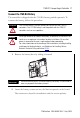
1769-L31 CompactLogix Controller 7 Connect the 1769-BA Battery The controller is shipped with the 1769-BA battery packed separately. To connect the battery, follow this procedure. ATTENTION WARNING The 1769-BA battery is the only battery you can use with the 1769-L31 controllers. The 1747-BA battery is not compatible with the 1769-L31 controllers and can cause problems. When you connect or disconnect the battery, an electrical arc can occur.
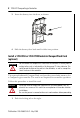
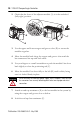
1769-L31 CompactLogix Controller 3. Insert the battery into the door, as shown. 4. Slide the battery door back until it clicks into position. Install a 1784-CF64 or 1784-CF128 Industrial CompactFlash Card (optional) ATTENTION Do not remove the CompactFlash card while the controller is reading from or writing to the card, as indicated by a flashing green CF status indicator. This could corrupt the data on the card or in the controller, as well as corrupt the latest firmware in the controller.
1769-L31 CompactLogix Controller 9 2. Insert the industrial CompactFlash card into the socket on the front of the controller, noting that the label of the CompactFlash card faces toward the left. 3. Match the orientation arrow on the card with the arrow on the front of the controller. 4. To remove the CompactFlash card, push the locking tab away from the CompactFlash card and pull the CompactFlash card from the socket.
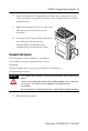
1769-L31 CompactLogix Controller 2. Check that the lever of the adjacent module (A) is in the unlocked (fully right) position. C A D B F E B 3. Use the upper and lower tongue-and-groove slots (B) to secure the modules together. 4. Move the module back along the tongue-and-groove slots until the bus connectors line up with each other. 5. Use your fingers or a small screwdriver to push the module’s bus lever back slightly to clear the positioning tab (C). 6.
1769-L31 CompactLogix Controller 11 Mount the System Maintain spacing from enclosure walls, wireways, and adjacent equipment. Allow 50 mm (2 in.) of space on all sides, as shown. This provides ventilation and electrical isolation. Dimensions are in mm (in.) in the figure. IMPORTANT ATTENTION When attaching the controller, power supply, and I/O modules, make sure the bus connectors are securely locked together to be sure of proper electrical connection.
1769-L31 CompactLogix Controller Product Dimensions Dimensions are in mm (in.) in the figure. Hole spacing tolerance is + 0.4 mm (0.016 in.) 15 mm (.59 in.) 67.5 mm (2.68 in.) 52.5 mm (2.06 in.) 70 mm (2.76 in.) 35 mm (1.38 in.) 132 mm (5.20 in.) 118 mm (4.65 in.) 52.5 mm (2.07 in.) IMPORTANT 35 mm (1.38 in.) 35 mm (1.38 in.) 35 mm (1.38 in.) 35 mm (1.38 in.) Compact I/O expansion cables have the same dimensions as the end caps. Expansion cables can be used on either the right or left end.
1769-L31 CompactLogix Controller 13 Panel Mounting Mount the controller to a panel by using two screws per module. Use M4 or #8 panhead screws. Mounting screws are required on every module. IMPORTANT The grounding tab, located where you install the mounting screws, enables the module to be grounded when it is panel-mounted. This procedure lets you use the assembled modules as a template for drilling holes in the panel. Due to module mounting hole tolerance, it is important to follow these procedures. 1.
1769-L31 CompactLogix Controller 6. Attach the modules to the panel by using the mounting screws. IMPORTANT If mounting more modules, mount only the last one of this group and put the others aside. This reduces remounting time when you are drilling and tapping the next group of modules. 7. Repeat steps 1...6 for any remaining modules. DIN Rail Mounting The controller can be mounted on the following DIN rails: EN 50 022 - 35 x 7.5 mm (1.38 x 0.30 in.) EN 50 022 - 35 x 15 mm (1.38 x 0.59 in.
1769-L31 CompactLogix Controller 15 Make RS-232 Connections to the Controller Connect the 9-pin female end of the serial cable to the serial port of the controller. WARNING If you connect or disconnect the serial cable with power applied to this module or the serial device on the other end of the cable, an electrical arc can occur. This could cause an explosion in hazardous location installations. Be sure that power is removed or the area is nonhazardous before proceeding.
1769-L31 CompactLogix Controller . Port 2: Mini-DIN 8 RS-232 Communication Rate Selector Switch DC Power Source Selector Switch Port 1: DB-9 RS-232, DTE Terminals for External 24V DC Power Supply 2. Select the appropriate cable. Isolator Use Cable No The 1756-CP3 cable attaches the controller directly to the controller.
69-L31 CompactLogix Controller 17 Isolator Use Cable Yes The 1761-CBL-AP00 cable (right-angle connector to controller) or the 1761-CBL-PM02 cable (straight connector to the controller) attaches the controller to port 2 on the 1761-NET-AIC isolator. The mini-DIN connector is not commercially available, so you cannot make this cable.
1769-L31 CompactLogix Controller Parameter Default Duplicate Packet (Message) Detect Enabled ACK Timeout 50 (x 20 ms) NAK Receive Limit 3 Retries ENQ Transmit Limit 3 Retries Data Bits 8 Stop Bits 1 Using the Channel 0 Default Communication Push Button IMPORTANT Only Channel 0 has a default communication push button. The Channel 0 default communication push button is located on the front of the controller in the lower right corner as shown in the illustration.
1769-L31 CompactLogix Controller 19 Install the Appropriate EDS Files If you have RSLinx software, version 2.42 or later, the most current EDS files were installed with the software. If you are using an earlier version of RSLinx software, you might need to install EDS files. You need EDS files for these devices: 1769-L31 controller 1769 CompactBus 1769 local adapter All of these EDS files, except for the 1769 CompactBus file, are updated for each firmware revision.
1769-L31 CompactLogix Controller The firmware is available with RSLogix 5000 software or you can download it from the support website at http://support.rockwellautomation.com. Follow these steps to download firmware from the support website. 1. In the left column (frame), click Technical Support. 2. Click Firmware Updates. 3. Select the firmware revision. 4. Enter the serial number of your RSLogix 5000 programming software.
1769-L31 CompactLogix Controller 21 Using the ControlFlash Utility to Load Firmware You can use the ControlFlash utility to load firmware through a serial connection. 1. Make sure the appropriate network connection is made before starting. 2. Start the ControlFlash utility. 3. From the Welcome dialog box, click Next. 4. Choose the catalog number of the controller, and click Next. 5. Expand the network until you see the controller.
1769-L31 CompactLogix Controller Using the AutoFlash Utility to Load Firmware You can use the AutoFlash utility to load firmware through a serial connection. 1. Make sure the appropriate network connection is made before starting. 2. Use RSLogix 5000 programming software to create a controller project. This automatically launches the AutoFlash utility. 3. Choose the catalog number of the controller, and click Next. 4. Expand the network until you see the controller.
1769-L31 CompactLogix Controller 23 Using a CompactFlash Card to Load Firmware If you have an existing controller that is already configured and has firmware loaded, you can store the current controller user program and firmware on the CompactFlash card and use that card to update other controllers. 1. Use RSLogix 5000 software to store the controller user program and firmware of a currently configured controller to the CompactFlash card. 2.
1769-L31 CompactLogix Controller Select the Controller’s Operating Mode Use the keyswitch on the front panel of the controller to determine the controller’s operating mode. Keyswitch Position RUN Description Upload projects. Run the program and enable outputs. You cannot create or delete tasks, programs, or routines. You cannot create or delete tags or edit online while the keyswitch is in the RUN position.
1769-L31 CompactLogix Controller 25 Controller Status Indicators Indicator Status Description RUN Off The controller is in Program or Test mode. Solid green The controller is in RUN mode. Off No tags contain I/O force values. I/O forces are inactive (disabled). Solid amber I/O forces are active (enabled). I/O force values may or may not exist. Flashing amber One or more input or output addresses have been forced to an On or Off state, but the forces have not been enabled.
1769-L31 CompactLogix Controller Indicator Status Description OK Off No power is applied. Flashing red If the controller is new, the controller requires a firmware update. If the controller is not new, a major fault occurred. To clear the fault, either: turn the keyswitch from Prog to RUN to PROG. Solid red The controller detected a nonrecoverable fault, so it cleared the project from memory. Follow these steps to recover. 1. Cycle power to the chassis. 2. Download the project. 3.
1769-L31 CompactLogix Controller 27 RS-232 Serial Port Status Indicators (Channel 0 and 1) Indicator Status Description DCH0 Off Channel 0 is configured differently than the default serial configuration. Solid green Channel 0 has the default serial configuration. Off No RS-232 activity. Flashing green RS-232 activity. Off No RS-232 activity. Flashing green RS-232 activity.
1769-L31 CompactLogix Controller Specifications CompactLogix Controller - 1769-L31 Attribute Value Communication ports CH0 - RS-232 RS-232 DF1, DH-485, ASCII fully isolated 38.4 Kbps max User memory 512 KB CH1 - RS-232 RS-232 DF1, DH-485 nonisolated 38.4 Kbps max Nonvolatile memory 1784-CF64 or 1784-CF128 CompactFlash card Number of I/O modules, max 16 I/O modules Number of I/O banks, max 3 banks Backplane current 330 mA at 5V DC 40 mA at 24V DC Power dissipation 2.
1769-L31 CompactLogix Controller 29 Environmental Specifications Attribute Value Operational Temperature IEC 60068-2-1 (Test Ad, Operating Cold) IEC 60068-2-2 (Test Bd, Operating Dry Heat) IEC 60068-2-14 (Test Nb, Operating Thermal Shock) 0...60 °C (32 ...140 °F) Storage Temperature IEC 60068-2-1 (Test Ab, Unpackaged Nonoperating Cold) IEC 60068-2-2 (Test Bb, Unpackaged Nonoperating Dry Heat) IEC 60068-2-14 (Test Na, Unpackaged Thermal Shock) -40...85 °C (-40 ...
1769-L31 CompactLogix Controller Certifications Certifications(1) (when product is marked) Value c-UL-us UL Listed Industrial Control Equipment, certified for US and Canada. See UL File E65584. UL Listed for Class I, Division 2 Group A,B,C,D Hazardous Locations, certified for U.S. and Canada. See UL File E194810. CE European Union 2004/108/EC EMC Directive, compliant with: EN 61326-1; Meas./Control/Lab.
1769-L31 CompactLogix Controller 31 Additional Resources These documents contain additional information concerning related Rockwell Automation products.
Rockwell Automation Support Rockwell Automation provides technical information on the Web to assist you in using its products. At http://support.rockwellautomation.com, you can find technical manuals, a knowledge base of FAQs, technical and application notes, sample code and links to software service packs, and a MySupport feature that you can customize to make the best use of these tools.