
Quick Start Owner's manual

Rockwell Automation Publication IASIMP-QS025B-EN-P - December 2012 25
Prepare the CompactLogix 5370 L2 Controller Hardware Chapter 1
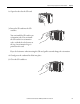
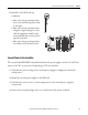
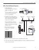
8. Install the 1769-ECR end cap
terminator.
a. Move the end cap terminator’s bus
lever to the unlocked position, that
is, the right.
b. Move the end cap terminator back
along the tongue-and-groove slots
with the rightmost module in the
system until the bus connectors line
up with each other.
c. Move the end cap terminator’s bus
lever fully to the left until it locks.
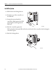
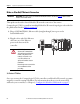
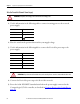
Connect Power to the Controller
The external 1606-XLDNET4 standard switched-mode power supply converts 115/230V AC
power to 24V DC to power the CompactLogix 5370 L2 controller.
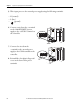
1. Verify that the power setting on the external power supply is configured to match the
voltage source.
2. Mount the external power supply on the DIN rail.
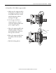
3. Verify that the wire you use to connect input power to the external power supply is
not powered.
4. Remove the clear plastic finger safe cover on the front of the power terminals.
01234567
8 9 10 11 12 13 14 15
01234567
8910
A0 B0 Z0
A1 B1 Z1
0 2 FUSE
13OK
11 12 13 14 15
HIGH SPEED
COUNTER
INOUT
DC
INPUT
24VDC
SINK\
SOURCE
24VDC
SOURCE
OUTPUT
DC
+24VDC COM FG
00
01
02
03
04
05
06
07
NC
+V
00
01
02
03
04
05
06
07
COM
0
COM
0
08
09
10
11
12
13
14
15
NC
+V
08
09
10
11
12
13
14
15
COM
1
COM
1
A0+
B0+
Z0+
A1+
B1+
Z1+
+V
OUT
1
OUT
0
COM COM
A0-
B0-
Z0-
A1-
B1-
Z1-
+V
0UT
3
V
in
0+
V
in
2+
V
OUT
0+
I
OUT
0+
V
OUT
1+
I
in
3+
V
in
1+
I
in
1+
I
in
1+
V
in
3+
CJC
-
CJC
+
V/I
in
1-
V/I
in
3-
V/I
in
0-
V/I
in
2-
I
in
0+
I
in
2+
OUT
2
COMCOM
DC IN
HSC
DC OUT
ANALOG
00:00:BC:2E:69:F6
L27ERM
QBFC1B