Quick Start CompactLogix 5370 L2 Controllers Catalog Numbers 1769-L24ER-QB1B, 1769-L24ER-QBFC1B, 1769-L27ERM-QBFC1B
Important User Information Solid-state equipment has operational characteristics differing from those of electromechanical equipment. Safety Guidelines for the Application, Installation and Maintenance of Solid State Controls (publication SGI-1.1 available from your local Rockwell Automation sales office or online at http://www.rockwellautomation.com/literature/) describes some important differences between solid-state equipment and hard-wired electromechanical devices.
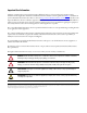
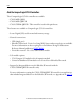
Where to Start Follow the path that matches your hardware and network configuration. Prepare the CompactLogix 5370 L2 Controller Hardware Required L27ERM QBFC1B 00:00:BC:2E:69:F6 +24VDC COM FG page 17 Required Prepare the Computer and Load Controller Firmware page 31 Optional POINT I/O™ Modules PowerFlex® 40 Drive PowerFlex 70 Drive Kinetix® 350 Drive PanelView™ Plus Terminal For more information on using each optional device, see Table 1 on page 11.
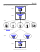
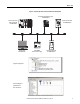
Where to Start How Hardware Is Connected This quick start, in use with the additional quick starts listed in Table 1 on page 11, describes possible control systems shown in Figure 1 and Figure 2.
Where to Start Figure 2 - CompactLogix 5370 L2 Controllers with a DeviceNet Network Distributed POINT I/O Modules with 1734-ADN Adapter CompactLogix 5370 L2 Control System with 1769-SDN Module PowerFlex 70 Drive with 20-COMM-D Adapter Computer with 1784-U2DN Cable 1606-XLDNET4 DeviceNet Power Supply PowerFlex 40 Drive with 22-COMM-D Adapter Application Configuration Network Configuration in RSNetWorx™ for DeviceNet Software Rockwell Automation Publication IASIMP-QS025B-EN-P - December 2012 5
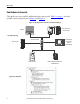
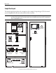
Where to Start Sample Panel Layout The sample panel layout shows the orientation of an example CompactLogix 5370 L2 control system using EtherNet/IP networks and DeviceNet networks. IMPORTANT The specific layout of CompactLogix 5370 L2 control systems varies by application. The following graphic is an example panel layout. The graphic shows a PowerFlex 40 drive used on a DeviceNet network. You can also use a PowerFlex 40 drive on an EtherNet/IP network.
Table of Contents Preface About the CompactLogix 5370 L2 Controllers . . . . . . . . . . . . . . . . . . . . . Choose to Integrate Optional Devices . . . . . . . . . . . . . . . . . . . . . . . . . . . . . Studio 5000 Environment . . . . . . . . . . . . . . . . . . . . . . . . . . . . . . . . . . . . . . . . Required Software . . . . . . . . . . . . . . . . . . . . . . . . . . . . . . . . . . . . . . . . . . . . . . . Parts List . . . . . . . . . . . . . . . . . . . . . . . . . . . . . . . . . . . . . . .
Table of Contents Chapter 4 Configure the DeviceNet Network Before You Begin. . . . . . . . . . . . . . . . . . . . . . . . . . . . . . . . . . . . . . . . . . . . . . . . . What You Need. . . . . . . . . . . . . . . . . . . . . . . . . . . . . . . . . . . . . . . . . . . . . . . . . . Follow These Steps . . . . . . . . . . . . . . . . . . . . . . . . . . . . . . . . . . . . . . . . . . . . . . . Apply Power to the DeviceNet Network . . . . . . . . . . . . . . . . . . . . . . . . . . .
Preface This quick start describes how to use CompactLogix 5370 L2 controllers to install a simple CompactLogix 5370 L2 control system and execute a task with a local expansion 1769 Compact I/O™ output module. The programming examples included are not complex, and offer solutions to verify that devices are functioning and communicating properly. IMPORTANT Consider the following points: • A typical CompactLogix 5370 L2 control system includes more components than listed in this quick start.
Preface About the CompactLogix 5370 L2 Controllers These CompactLogix 5370 L2 controllers are available: • 1769-L24ER-QB1B • 1769-L24ER-QBFC1B • 1769-L27ERM-QBFC1B - This controller is used in this quick start. These features are available on CompactLogix 5370 L2 controllers: • Secure Digital (SD) card for nonvolatile memory storage • Network connections: – – – • I/O module options: – – • USB (single port) EtherNet/IP network - Device-level ring (DLR), linear, and star topologies are available.
Preface This graphic shows a CompactLogix 5370 L2 control system that matches the system you will install after completing steps. L27ERM QBFC1B 00:00:BC:2E:69:F6 +24VDC COM FG Choose to Integrate Optional Devices You can integrate multiple optional devices into a CompactLogix 5370 L2 control system. You can use these devices on DeviceNet or EtherNet/IP networks. This table describes optional devices you might use in a CompactLogix 5370 L2 control controller system and what resources to use for each.
Preface Table 1 - Devices in Logix5000 Control System Device Type Product Line(1) Additional Resource with More Information Drives PowerFlex40 Logix5000 Control Systems: Connect PowerFlex 40 Drives over a DeviceNet Network Quick Start, publication IASIMP-QS028 Logix5000 Control Systems: Connect PowerFlex 40 Drives over an EtherNet/IP Network Quick Start, publication IASIMP-QS029 PowerFlex 70 Logix5000 Control Systems: Connect PowerFlex 70 Drives over a DeviceNet Network Quick Start, publication IASI
Preface Studio 5000 Environment The Studio 5000™ Engineering and Design Environment combines engineering and design elements into a common environment. The first element in the Studio 5000 environment is the Logix Designer application. The Logix Designer application is the rebranding of RSLogix™ 5000 software and will continue to be the product to program Logix5000™ controllers for discrete, process, batch, motion, safety, and drive-based solutions.
Preface Required Software Before attempting to complete any of the tasks described in this publication, verify that your computer meets the following operating system and service pack compatibility requirements: • Microsoft Windows 7 Professional (64-bit) with Service Pack 1 • Microsoft Windows 7 Home Premium (64-bit) with Service Pack 1 • Microsoft Windows 7 Home Premium (32-bit) with Service Pack 1 • Microsoft Windows Server 2008 R2 Standard Edition with Service Pack 1 If your computer does not meet the
Preface Parts List Table 3 lists the hardware used in this quick start. The minimum hardware you need depends on the options and examples you choose to complete. For example, if you do not intend to use a DeviceNet network to complete tasks described in some publications listed in Table 1, you do not need the hardware related to installing a DeviceNet network. Specific hardware requirements are listed at the beginning of each chapter. Table 3 - Parts Used with This Quick Start Quantity Cat. No.
Preface Additional Resources These documents contain additional information concerning related products from Rockwell Automation. Resource Description CompactLogix 5370 Controllers User Manual, publication 1769-UM021 Describes how to design, install, operate, and troubleshoot a CompactLogix 5370 control system.
Chapter 1 Prepare the CompactLogix 5370 L2 Controller Hardware This chapter describes the hardware required to install your CompactLogix 5370 L2 system. Before You Begin Determine which networks your control system uses. You can use CompactLogix 5370 L2 controllers on an EtherNet/IP network and on a DeviceNet network. What You Need Table 4 lists the hardware components used in this chapter.
Chapter 1 Prepare the CompactLogix 5370 L2 Controller Hardware Table 4 - Parts Used with This Quick Start Quantity Cat. No.
Prepare the CompactLogix 5370 L2 Controller Hardware Chapter 1 Install the Network Before you install your CompactLogix 5370 L2 control hardware, you must install the network on which it will operate, that is, an EtherNet/IP or DeviceNet network. For more information on installing either of these networks, see the publications listed in the following table.
Chapter 1 Prepare the CompactLogix 5370 L2 Controller Hardware Install the Secure Digital Card The Secure Digital (SD) card provides nonvolatile storage for the CompactLogix 5370 L2 controller. You can use the SD card for multiple functions in your application, for example, storing Logix Designer projects on the SD card or loading Logix Designer projects from an SD card.
Prepare the CompactLogix 5370 L2 Controller Hardware Chapter 1 2. Open the door for the SD card. 3. Insert the SD card into the SD card slot. You can install the SD card in one orientation only. You can install the SD card in one orientation only—with the beveled corner at the top. An orientation logo is printed on the card. If you feel resistance when inserting the SD card, pull it out and change the orientation. 4. Gently press the card until it clicks into place. 5. Close the SD card door.
Chapter 1 Prepare the CompactLogix 5370 L2 Controller Hardware Install the System 1. Pull the bottom locking tabs out. L27ERM 5 6 A0 B0 Z0 7 15 3 6 7 10 11 12 13 14 15 10 11 12 13 14 4 5 2. Hook the top of the controller on the DIN rail.
Prepare the CompactLogix 5370 L2 Controller Hardware Chapter 1 6. Install the 1769-OB16 output module. a. Make sure the output module’s locking tabs are pulled out and the module’s bus lever is in the unlocked position, that is, leaning to the right. L27ERM 5 6 6 7 11 12 13 14 15 10 11 12 13 14 4 5 00 08 01 09 B0+ B0- 02 10 Z0+ Z0- 03 11 A1+ A1- 04 12 B1+ B1- 05 13 Z1+ Z1- COM COM 0 1 +V +V OUT OUT 0 2 OUT 0UT 1 3 NC NC COM COM 06 14 00 08 01 09 02 10 03 11 04 12 06 14 07 15 c.
Chapter 1 Prepare the CompactLogix 5370 L2 Controller Hardware 7. Install the 1769-SDN scanner module. a. Make sure the scanner module’s locking tabs are pulled out. b. Make sure the scanner module’s bus lever is in the unlocked position, that is, leaning to the right. c. Use the upper and lower tongueand-groove slots to secure the scanner module and power supply together. d. Move the scanner module back along the tongue-and-groove slots until the bus connectors line up with each other. e.
Prepare the CompactLogix 5370 L2 Controller Hardware Chapter 1 8. Install the 1769-ECR end cap terminator. a. Move the end cap terminator’s bus lever to the unlocked position, that is, the right. b. Move the end cap terminator back along the tongue-and-groove slots with the rightmost module in the system until the bus connectors line up with each other. c. Move the end cap terminator’s bus lever fully to the left until it locks.
Chapter 1 Prepare the CompactLogix 5370 L2 Controller Hardware 5.
Prepare the CompactLogix 5370 L2 Controller Hardware Chapter 1 Make Network Connections You can make these connections to a CompactLogix 5370 L2 controller: • Make a USB Connection • Make an EtherNet/IP Network Connection • Make a DeviceNet Network Connection Make a USB Connection IMPORTANT You must use RSLinx Classic software, version 3.51.00 or later, with your CompactLogix 5370 L2 controllers. With this software version, there is no need to install an RSLinx Classic software driver.
Chapter 1 Prepare the CompactLogix 5370 L2 Controller Hardware Make an EtherNet/IP Network Connection IMPORTANT ATTENTION: This section assumes you installed an EtherNet/IP network as described on page 19 and the network includes a 1783-EMS08T switch. This quick start describes a basic EtherNet/IP network connection. You can use CompactLogix 5370 L2 controllers in multiple EtherNet/IP network topologies as described in the publications listed in Table 5 on page 19. 1.
Prepare the CompactLogix 5370 L2 Controller Hardware Chapter 1 Make a DeviceNet Network Connection 1. Attach and lock the 1606-XLDNET8 DeviceNet power supply to the DIN rail. 1606-X POWE AC 120 AC 240 The power supply uses a locking tab at the top that you push down to secure it to the DIN rail. 2. Assemble the DeviceNet network cable system using the KwikLink flat cable, terminators, and sealed micro connectors for each device.
Chapter 1 Prepare the CompactLogix 5370 L2 Controller Hardware Wire the DeviceNet Network Power Supply WARNING: Verify that all incoming power is turned off before wiring power. 1. Use the information in the following table to connect incoming power to the network power supply. Connect To V AC COM N (neutral) 120/240V AC L (line) Ground 2. Place the switch in the position that matches your supply voltage. 3.
Chapter 2 Prepare the Computer and Load Controller Firmware In this chapter, you install the necessary programming and configuration software, configure network communication on your computer, and load firmware on your controller. Before You Begin Before you begin, complete these tasks: • Verify that your computer meets the software’s system requirements for installation and use of the software listed in Table 6.
Chapter 2 Prepare the Computer and Load Controller Firmware What You Need Table 6 lists the components you use in this chapter. Table 6 - What You Need to Prepare the Computer Component Description Studio 5000 environment Environment that combines engineering and design elements into a common environment. Logix Designer application Software used to create a project the CompactLogix 5370 L2 controller uses in your application.
Prepare the Computer and Load Controller Firmware Chapter 2 Follow These Steps Install the Studio 5000 Environment page 34 Configure an EtherNet/IP Driver in RSLinx Classic Software page 37 Set the IP Address for the Computer page 39 Load the Controller Firmware page 42 Optional Install Additional Software page 46 Rockwell Automation Publication IASIMP-QS025B-EN-P - December 2012 33
Chapter 2 Prepare the Computer and Load Controller Firmware Install the Studio 5000 Environment The Studio 5000 environment, version 21.00.00, installation process is configured so that, among other software applications, RSLinx Classic software, version 3.51.00, and RSNetWorx for DeviceNet software, version 21.00.00, are automatically installed. The automatic installation option is enabled by default.
Prepare the Computer and Load Controller Firmware Chapter 2 3. Use the default selections and click Install. 4. Read the license agreement carefully. 5. Click Accept All. The installation process begins. When installation is complete, your computer will have the software necessary required to complete the tasks described in this publication.
Chapter 2 Prepare the Computer and Load Controller Firmware Among other software, your computer will have the following: • Studio 5000 Environment, version 21.00.00 • • The Studio 5000 Environment, version 21.00.00 includes Logix Designer application, version 21.00.00. RSLinx Classic software, version 3.51.00 RSNetWorx for DeviceNet, version 21.00.00 You are prompted to activate the software.
Prepare the Computer and Load Controller Firmware Chapter 2 Configure an EtherNet/IP Driver in RSLinx Classic Software 1. Start the software. 2. From the Communications menu, choose Configure Drivers. The Configure Drivers dialog box appears. 3. From the Available Driver Types pull-down menu, choose EtherNet/IP Driver or Ethernet devices and click Add New. We recommend that you use EtherNet/IP Driver. The Add New RSLinx Classic Driver dialog box appears.
Chapter 2 Prepare the Computer and Load Controller Firmware 4. Click OK to keep the default name. The Configure driver:AB_ETHIP-x dialog box appears. The full name of the dialog box varies by what driver type was chosen in step 3. This example uses the EtherNet/IP Driver; the driver name is AB_ETHIP-1. 5. Select an Ethernet card and click OK. This new driver is available. 6. Verify that the driver’s Status is Running and click Close.
Prepare the Computer and Load Controller Firmware Chapter 2 Set the IP Address for the Computer Your computer requires an Internet Protocol (IP) address to operate on an EtherNet/IP network. The IP address uniquely identifies the controller and is in the form xxx.xxx.xxx.xxx where each xxx is a number from 000…254 with some exceptions for reserved values. A computer’s IP address can be set automatically or manually. The manual option is typically used with isolated networks.
Chapter 2 Prepare the Computer and Load Controller Firmware 3. Right-click Local Area Connection and choose Properties. 4. On the Networking tab, choose Internet Protocol Version 4 (TCP/IPv4) and click Properties.
Prepare the Computer and Load Controller Firmware Chapter 2 5. Select Use the following IP address and enter an IP address and Subnet mask for your computer. 6. Record the IP address and subnet mask. 7. Click OK. 8. Close the Local Area Connection Properties dialog box.
Chapter 2 Prepare the Computer and Load Controller Firmware Load the Controller Firmware IMPORTANT This section assumes that you downloaded the controller firmware from the Rockwell Automation technical support website to install on your CompactLogix 5370 L2 controller. If not, download the firmware before following the steps in this section. The firmware is available with the Logix Designer application or you can download it from the support website. Go to http://www.rockwellautomation.
Prepare the Computer and Load Controller Firmware Chapter 2 4. Click Next. 5. Select the controller catalog number and click Next.
Chapter 2 Prepare the Computer and Load Controller Firmware 6. Expand the USB driver, and choose your controller. 7. Click OK. 8. Verify that your controller’s mode switch is in the REM position. RUN REM PROG 9. Choose the desired firmware revision and click Next. TIP 44 Consider the following: • If the Current Revision matches the firmware revision shown in the box below it, click Cancel. You are finished with this task. • This example uses firmware revision 21.001.23.
Prepare the Computer and Load Controller Firmware Chapter 2 10. To start the firmware update, click Finish and then click Yes. Before the firmware upgrade begins, you an Attention dialog box. Take the appropriate action for your application. In this example, the upgrade continues when OK is clicked. After the controller is updated, the status dialog box displays the message Update complete.
Chapter 2 Prepare the Computer and Load Controller Firmware 11. Click OK. 12. To close the ControlFLASH software, click Cancel and then click Yes. Install Additional Software Depending on your application, you may need to install additional software. For example, if you are integrating a PanelView Plus terminal into your system, you must install the following: • RSLinx Enterprise software IMPORTANT • 46 You must install this software before you install any other additional software.
Chapter 3 Configure the EtherNet/IP Network In this chapter, you assign an IP address to your CompactLogix 5370 L2 controller. This quick start does not use other devices on the EtherNet/IP network. It is not uncommon, however, to use other devices on an EtherNet/IP network in a CompactLogix 5370 L2 control system. If you were to do so, for example, use PanelView Plus terminal on an EtherNet/IP network, you need to assign an IP address to each device.
Chapter 3 Configure the EtherNet/IP Network Before You Begin Before you begin, complete these tasks: • The tasks described in Chapter 1, Prepare the CompactLogix 5370 L2 Controller Hardware on page 17, including the following: – – – – Install the EtherNet/IP network. Install the controller and the local expansion 1769-OB16 output module. Wire power to the controller. Make network connections.
Configure the EtherNet/IP Network Chapter 3 What You Need Table 7 lists the software components you use in this chapter. Table 7 - What You Need to Configure the EtherNet/IP Network Component Description Studio 5000 environment Environment that combines engineering and design elements into a common environment. Logix Designer application Software used to create a project the CompactLogix 5370 L2 controller used in your application.
Chapter 3 Configure the EtherNet/IP Network Assign an IP Address to the Controller over a USB Connection At initial powerup, the CompactLogix 5370 L2 controller does not have an IP address. Use RSLinx Classic software over a USB connection to assign an IP address. The following steps will work only if the computer with RSLinx Classic software is connected to the controller via a USB connection.
Configure the EtherNet/IP Network Chapter 3 5. Click the Port Configuration tab. 6. For Network Configuration Type, click Static to permanently assign this configuration to the port. IMPORTANT The controller’s default configuration is Dynamic. When the controller is configured for Dynamic, on a power cycle, it clears the current IP address and resumes sending BOOTP requests. 7. Enter the IP address and Network Mask for the controller. 8. Enter other network parameters, if desired. 9. Click OK.
Chapter 3 Configure the EtherNet/IP Network Notes: 52 Rockwell Automation Publication IASIMP-QS025B-EN-P - December 2012
Chapter 4 Configure the DeviceNet Network In this chapter, you configure the DeviceNet node address for the 1769-SDN scanner module. You also create the RSNetWorx for DeviceNet file that stores network configuration. IMPORTANT Not all tasks described in this quick start are required to complete the final task, that is, use ladder logic to test a 1769-OB16 output module as described beginning on page 63. For example, you do not need a DeviceNet configuration file to test the module.
Chapter 4 • • Configure the DeviceNet Network The tasks described in Chapter 2, Prepare the Computer and Load Controller Firmware on page 31, including the following: – Install the Studio 5000 environment and RSLinx Classic software. – Logix Designer application is installed when you install the Studio 5000 environment. Load firmware on the controller. Verify that power is applied to all devices. What You Need Table 8 lists the components you use in this chapter.
Configure the DeviceNet Network Chapter 4 Follow These Steps Apply Power to the DeviceNet Network 1606-X POWER L SUPPLY AC 120V AC 240V Input AC 100 -120/200 -240 N L Isolate powe r befo re disco page 56 Outpu V DC ok nnecting t 200W Lim DC 24V ited Pow er / 8A + – DC ok Set the 1769-SDN Scanner Module’s Node Address page 57 Create a DeviceNet Configuration File page 59 Rockwell Automation Publication IASIMP-QS025B-EN-P - December 2012 55
Chapter 4 Configure the DeviceNet Network Apply Power to the DeviceNet Network In this quick start, the CompactLogix 5370 L2 control system uses a 1606-XLDNET8 DeviceNet power supply to power the DeviceNet network. You completed the tasks described in Make a DeviceNet Network Connection on page 29 to install the power supply and other components in the DeviceNet network, such as a KwikLink sealed terminator on each end of the KwikLink flat cable.
Configure the DeviceNet Network Chapter 4 Set the 1769-SDN Scanner Module’s Node Address 1. Start the software. 2. From the Tools menu, choose Node Commissioning. 3. Click Browse. When the Device Selection dialog box appears, you can browse to the 1769-SDN scanner module over an EtherNet/IP network or USB connection. This example uses an EtherNet/IP network connection.
Chapter 4 Configure the DeviceNet Network 4. Under the AB_ETHIP-1 driver, expand the path to the 1769-SDN scanner module as shown in the example graphic. 5. Click OK. 6. If you receive a linking device warning, click Yes. The Node Commissioning dialog box is populated with the 1769-SDN module’s current settings. 7. Enter a node address of 1 for the 1769-SDN scanner module and click Apply.
Configure the DeviceNet Network Chapter 4 The Address is applied and is confirmed in the Messages box. 8. Record the node address. 9. Click Close. Create a DeviceNet Configuration File 1. From the File menu, choose New. 2. Click Who Active to go online.
Chapter 4 Configure the DeviceNet Network 3. Expand the networks to the appropriate DeviceNet network. In this example, the network is Port 2, DeviceNet. 4. If desired, record following information about the 1769-SDN scanner module: • • Slot number = 5 DeviceNet network node number = 1 Slot number in the CompactBus = 5 DeviceNet network node number = 1 If you do not need this information, skip to step 5. 5. Click OK.
Configure the DeviceNet Network Chapter 4 6. Click OK when the alert about uploading or downloading device information. RSNetWorx for DeviceNet software browses the network and shows the 1769-SDN scanner module at DeviceNet network node number 1. 7. Right-click the 1769-SDN scanner module and choose Properties. 8. Click the Module tab. The information for your DeviceNet scanner module may vary from what is shown here.
Chapter 4 Configure the DeviceNet Network 9. Click Download. All configuration is cleared from the 1769-SDN scanner module, and the software is synchronized with the module. 10. From the Platform pull-down menu, choose CompactLogix. 11. Enter the slot number of the 1769-SDN scanner module. 12. Click OK. 13. Save the file and record the file name and path. This quick start uses the example file name DeviceNet.dnt. 14. Close RSNetWorx for DeviceNet software.
Chapter 5 Create a Logix Designer Project In this chapter you create a Logix Designer project. In the project you use ladder logic to create a push button that controls a light on a digital output module. You learn how to complete the following tasks: • Create a Logix Designer project. • Configure your 1769-L27ERM-QBFC1B controller. • Add a local expansion module to the project. • Add a 1769-SDN scanner module to the project. • Add ladder logic to the project to test the local expansion module.
Chapter 5 Create a Logix Designer Project Before You Begin Before you begin, complete these tasks: • The tasks described in Chapter 1, Prepare the CompactLogix 5370 L2 Controller Hardware on page 17, including the following: – – – • Install the EtherNet/IP network. Install the controller and the local expansion module. Wire power to the controller.
Create a Logix Designer Project Chapter 5 Follow These Steps Create a Project page 66 Configure the Controller page 68 Add the Local Expansion Module page 70 Add the 1769-SDN Scanner Module (optional) page 71 Add Ladder Logic to Use the Local 1769-OB16 Module page 74 Download the Project to the Controller and Test the Logic page 77 Rockwell Automation Publication IASIMP-QS025B-EN-P - December 2012 65
Chapter 5 Create a Logix Designer Project Create a Project 1. Start the application. 2. Click New Project. The New Project dialog box appears.
Create a Logix Designer Project Chapter 5 3. Choose your controller and name the project. 4. Click Next. 5. Choose a Security Authority and click Finish. For the purposes of this publication, we recommend that you choose No Protection, as shown.
Chapter 5 Create a Logix Designer Project Configure the Controller 1. Verify that your controller’s mode switch is in the REM position. RUN REM PROG 2. Click the RSWho icon. 3. In the Who Active dialog box, expand the path to the controller and select it. 4. Click Set Project Path. 5. Click Download. 6. Click Download again when the Download dialog box appears. IMPORTANT 68 After the download is complete, the controller goes online.
Create a Logix Designer Project Chapter 5 7. If prompted, click Yes to change the controller mode to Remote Run. 8. Expand the I/O Configuration tree. 9. Right-click the controller and choose Properties. 10. Use the tabs on the Controller Properties dialog box to configure the controller. The IP address is set on the Internet Protocol tab.
Chapter 5 Create a Logix Designer Project Add the Local Expansion Module 1. Right-click Expansion I/O and choose New Module. The Select Module Type dialog box appears. 2. Select the 1769-OB16 Compact I/O output module and click Create. The New Module dialog box appears for the module created.
Create a Logix Designer Project Chapter 5 3. Use the tabs to create the parameters for the I/O module. IMPORTANT For the purposes of this quick start, make sure you change the Module Definition parameters so Electronic Keying is set to Disable Keying. 4. When the module configuration is complete, click OK. The module is added to the I/O Configuration.
Chapter 5 Create a Logix Designer Project 2. Select the 1769-SDN scanner module and click Create. 3. Select the 1769-SDN scanner module’s major revision and click OK. 4. When the New Module dialog box appears, configure the 1769-SDN scanner module. 5. Check the Open Module Properties checkbox and click OK. Additional tabs with configurable parameters appear.
Create a Logix Designer Project Chapter 5 6. On the RSNetWorx tab, click Browse to find the configuration (.dnt) file created in Create a DeviceNet Configuration File on page 59. This quick start uses New DeviceNet.dnt. 7. Click OK. The module is added to the I/O Configuration. 8. Save the project.
Chapter 5 Create a Logix Designer Project Add Ladder Logic to Use the Local 1769-OB16 Module 1. Expand the Tasks folders. 2. Right-click MainRoutine and choose Open or double-click on Main Routine. A blank MainRoutine opens. 3. From the Element Toolbar, drag and drop an Examine On and an Output Energize element onto the rung. 4. Double-click the ? in the Examine On element. 5. Type PB (for push button). 6. Press Enter.
Create a Logix Designer Project Chapter 5 7. Right-click PB and choose New ‘PB’. 8. Click Create and Close. 9. Double-click the ? in the Output Energize element. 10. Name the Output Energize element OB16_Light. IMPORTANT Do not use spaces in the tag name. Use underscores (_) instead. 11. Press Enter.
Chapter 5 Create a Logix Designer Project 12. Right-click the OB16_Light tag name and choose New OB16_Light. OB16_Light is an alias tag for the I/O point tag name. With an alias tag, you assign a simple name to a physical I/O point address. 13. From the Type pull-down menu, choose Alias. 14. In the Alias For pull-down menu, browse to the local 1769-OB16 output module choose any bit. This example uses Local:4:O.Data.0. 15. Click Create and Close. 16.
Create a Logix Designer Project Chapter 5 Download the Project to the Controller and Test the Logic 1. From the mode pull-down menu, choose Download. 2. When the dialog box appears with information about the download, click Download. 3. Click Yes to change the controller mode to Remote Run. 4. Move the mode switch on your controller to RUN. RUN REM PROG 5. Select the PB Examine On instruction. 6. Press Ctrl+T to toggle the state from 0 to 1, or Off to On. 7.
Chapter 5 Create a Logix Designer Project Notes: 78 Rockwell Automation Publication IASIMP-QS025B-EN-P - December 2012
Appendix A Understanding Other Application Options This chapter describes two application options available with a CompactLogix 5370 L2 controller: • Using the controller in a DLR network topology • Using the controller in an application that includes Integrated Motion on an EtherNet/IP network - 1769-L27ERM-QBFC1B only IMPORTANT This chapter does not describe specific steps required to use the CompactLogix 5370 L2 controller in applications with DLR networks or Integrated Motion over an EtherNet/IP
Appendix A Understanding Other Application Options DLR Network Topology A DLR network topology is a single-fault-tolerant ring network in which DLR-capable Allen-Bradley devices use embedded technology and dual EtherNet/IP ports to establish a network that is resilient to single points of failure, recovers faster when single faults occur, and does not require switches.
Understanding Other Application Options Appendix A Follow These Steps IN DC INPUT 24VDC SINK\ SOURCE DC INPUT IN 1 2 FUSE 2 FUSE 3 OK OK 3 Z0+ Z0- 02 10 A1+ A1- 03 11 B1+ B1- 04 12 Z1+ Z1- 05 13 +V +V OUT OUT 0 2 OUT 0UT 1 3 COM COM 06 14 07 15 V V in in 0+ 2+ I I in in 0+ 2+ V/I V/I in in 0- 2V CJC in + 3+ CJC inI - 3+ V V/I in in 1+ 3- 01 09 02 10 03 11 04 12 I V/I in in 1+ 1V V OUT OUT 0+ 1+ I I OUT in 0+ 1+ 05 13 06 14 07 15 COM COM 0 1 COM COM ANALOG DC OUT COM COM 0 0 1 B0
Appendix A Understanding Other Application Options Integrated Motion on the EtherNet/IP Network Integrated Motion on the EtherNet/IP network is an integrated motion solution on a standard, unmodified EtherNet/IP network that delivers high performance with lower costs and simpler design or configuration when compared to traditional, multi-network motion applications. The 1769-L27ERM-QBFC1B controller supports Integrated Motion on an EtherNet/IP network.
Index Numerics 1485A-T1E4 KwikLink terminator/resistor 15, 17 1485C-P1E75 KwikLink cable 15, 17 1485K-P1F5-C KwikLink QD cordset micro right-angle male 15, 18 1485P-P1E4-R5 KwikLink sealed micro connector 15, 17 1485T-P1E4-B KwikLink power tap module 15, 18 1585J-M8PBJM-2 RJ45-to-RJ45 patchcord Ethenet cable 15, 17 1606-XLDNET4 power supply 15, 17 1606-XLDNET8 power supply 15, 17, 29, 56 1769-OB16 output module 15, 17, 70 installation 23 1769-SDN scanner module 10, 15, 17, 71 installation 24 set node addres
Index M motion support Integrated Motion on the EtherNet/IP network 79, 82 N networks configure an EtherNet/IP network 47-52 connect to a DeviceNet network 29 connect to an EtherNet/IP network 28 DeviceNet 3, 53-62 EtherNet/IP 3 USB connection 27 node address set in RSNetWorx for DeviceNet software 5759 nonvolatile memory SD card 10 P panel layout sample 6 PanelView Plus terminals 12 POINT I/O modules 11 power connect to controller 25 power supply 1606-XLDNET4 power supply 15, 17 1606-XLDNET8 power suppl
Rockwell Automation Support Rockwell Automation provides technical information on the Web to assist you in using its products. At http://www.rockwellautomation.com/support/, you can find technical manuals, a knowledge base of FAQs, technical and application notes, sample code and links to software service packs, and a MySupport feature that you can customize to make the best use of these tools.