
Installation Instructions Manual

CompactLogix Controller 21
Rockwell Automation Publication 1769-IN082C-EN-P - February 2013
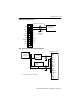
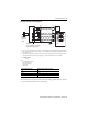
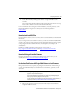
Differential Input Wiring Diagram
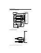
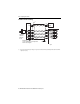
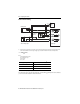
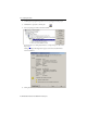
Single-ended Sensor/Transmitter Types Wiring Diagram
+
–
V in 1+
V in 3+
V in 0+
V/I in 0-
I in 1+
I in 3+
V/I in 1 -
I in 0+
I in 2+
V in 2 +
V/I in 3 -
V/I in 2-
ANLG Com
ANLG Com
V out 1+
I out 1+
V out 0+
I out 0+
Earth ground the
shield locally at the
module.
Differential Voltage
Tran sm it te r
Belden 8761 Cable (or equivalent)
+
V in 0+
V/I in 0 -
I in 0+
V in 1+
V/I in 1-
I in 1+
V in 2+
V/I in 2-
I in 2+
ANLG Com
ANLG Com
V in 3+
I out 0+
V out 0+
I out 1 +
V out 1+
V/I in 3-
I in 3+
+
+
-
Current
Tran sm itter
Sensor/
Tran sm it te r
Power Supply
Voltage Transmitter
Signal
Signal
Ground
1769-IF4XOF2 Terminal Block
The sensor power supply must be rated at Class 2.