Installation Instructions CompactLogix Packaged Controllers Catalog Numbers 1769-L23E-QB1B, 1769-L23E-QBFC1B, 1769-L23-QBFC1B Topic Page Important User Information 2 Verify Compatibility 6 Before You Begin 6 Installation Checklist 8 Packaged Controller Dimensions 9 Install the Battery 11 Connect Expansion Modules (optional) 12 Panel Mount the System 14 DIN-rail Mount the System 14 Grounding Considerations 15 Wiring Power to the System 15 Wire the I/O Removable Terminal Blocks 17 C
CompactLogix Controller Important User Information Solid-state equipment has operational characteristics differing from those of electromechanical equipment. Safety Guidelines for the Application, Installation and Maintenance of Solid State Controls (Publication SGI-1.1 available from your local Rockwell Automation® sales office or online at http://www.rockwellautomation.com/literature/) describes some important differences between solid-state equipment and hard-wired electromechanical devices.
CompactLogix Controller 3 Environment and Enclosure WARNING: This equipment is intended for use in a Pollution Degree 2 industrial environment, in overvoltage Category II applications (as defined in IEC publication 60664-1), at altitudes up to 2000 meters (6562 ft) without derating. This equipment is considered Group 1, Class A industrial equipment according to IEC/CISPR Publication 11.
CompactLogix Controller North American Hazardous Location Approval The following information applies when operating this Informations sur l’utilisation de cet équipement en equipment in hazardous locations. environnements dangereux. Products marked "CL I, DIV 2, GP A, B, C, D" are suitable for use in Class I Division 2 Groups A, B, C, D, Hazardous Locations and nonhazardous locations only. Each product is supplied with markings on the rating nameplate indicating the hazardous location temperature code.
CompactLogix Controller 5 European Hazardous Location Approval European Zone 2 Certification (The following applies when the product bears the Ex or EEx Marking.
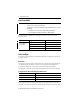
CompactLogix Controller Verify Compatibility IMPORTANT The series B controllers are compatible only with the controller firmware and the RSLogix 5000 software versions as indicated in the table below.
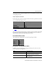
CompactLogix Controller 7 the packaged controller’s maximum available bus current, you are within the expansion I/O limit of your packaged controller. Example of Expansion I/O Calculation In this example, these expansion I/O modules and bus current draws are planned for use with the 1769-L23E-QBFC1B packaged controller.
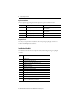
CompactLogix Controller Replacement Parts These CompactLogix packaged controller replacement parts are available for order. Catalog No.
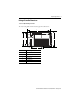
CompactLogix Controller 9 Packaged Controller Dimensions 1769-L23E-QB1B Packaged Controller The 1769-L23E-QB1B controller has these approximate dimensions. a CompactLogix L23E b d c e Measurement f Dimension, approximate a 185.2 mm (7.29 in.) b 123.86 mm (4.88 in.) c 118 mm (4.65 in.) d 132 mm (5.20 in.) e 132.9 mm (5.23 in.) f 18 mm (0.71 in.
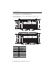
CompactLogix Controller 1769-L23E-QBFC1B and 1769-L23-QBFC1B Packaged Controllers The 1769-L23E-QBFC1B and 1769-L23-QBFC1B packaged controllers have these approximate dimensions. a CompactLogix L23E b d c e g f a RUN FORCE BATT b CompactLogix L23 I/O OK DCH 0 d c e Measurement(1) (1) Dimension, approximate a 249.25 mm (9.81 in.) b 123.86 mm (4.88 in.) c 118 mm (4.65 in.) d 132 mm (5.20 in.) e 98.475 mm (3.88 in.) f 98.475 mm (3.88 in.) g 18 mm (0.71 in.
CompactLogix Controller 11 Minimum Spacing Requirements When using any of the CompactLogix packaged controllers, maintain spacing from enclosure walls, wireways, and adjacent equipment. Allow 50 mm (1.97 in.) of space on all sides, as shown. This provides ventilation and electrical isolation. 50 mm (1.97 in.) 50 mm (1.97 in.) RUN FORCE BATT I/O OK DCH 0 CompactLogix L23 50 mm (1.97 in.) 50 mm (1.97 in.) Install the Battery Complete these steps to install the battery on your packaged controller.
CompactLogix Controller 4. Close the battery door. Connect Expansion Modules (optional) If using expansion modules with your packaged controller, complete these steps to attach the modules. 1. Remove the end cap by unlocking it and sliding it forward. 2. Align the tongue-and-groove slots of the expansion module with those on the right end of the packaged controller. 3. Slide the module onto the packaged controller.
CompactLogix Controller 13 4. Close the locking tab on the top of the module. 5. If using another expansion module, complete steps 2…4 for the second module. 6. Align the tongue-and-groove slots of the end cap with those on the right of the packaged controller or expansion module. 7. Close the locking tab located on the top of the end cap.
CompactLogix Controller Panel Mount the System To mount your system to a panel, complete these steps. 1. Using the assembled system as a template, carefully mark the center of all mounting holes on the panel. 2. Remove the system and drill and tap the mounting holes for the recommended M4 or #8 screws. 3. Place the grounding panel (if used) and CompactLogix system on the panel to check for proper hole alignment. 4.
CompactLogix Controller 15 1. Before mounting the packaged controller on a DIN rail, close the DIN-rail latches. 2. Press the DIN-rail mounting area of the packaged controller against the DIN rail. The latches momentarily open and lock into place on the DIN rail. 3. Press the DIN rail mounting area of the packaged controller against the DIN rail. The latches momentarily open and lock into place on the DIN rail.
CompactLogix Controller IMPORTANT To comply with the CE Low Voltage Directive (LVD), this equipment and all connected I/O must be powered from a source compliant with one of the following: • safety extra low voltage (SELV) • protected extra low voltage (PELV) CompactLogix L23E No Connection No Connection +24 V DC DC Neutral System Power Ground Power Wire Size and Terminal Screw Torque Wire Type Solid or stranded Cu: 75 °C (167 °F) Wire Size Terminal Screw Torque 0.25... 2.5 mm2 (22...
CompactLogix Controller 17 Wire the I/O Removable Terminal Blocks WARNING: • When you connect or disconnect the Removable Terminal Block (RTB) with field side power applied, an electrical arc can occur. This could cause an explosion in hazardous location installations. • If you connect or disconnect wiring while the field-side power is on, an electrical arc can occur. This could cause an explosion in hazardous location installations.
CompactLogix Controller DC Inputs Wiring Diagram(1) + DC (sinking) - DC (sourcing) 24V DC + DC (sinking) - DC (sourcing) (sinking) - +DCDC(sinking) DC (sourcing) (sourcing) +- DC 24V DC - DC (sinking) + DC (sourcing) (1) Sinking/Sourcing Inputs - Sourcing/sinking describes the current flow between the I/O and the field device. Sourcing I/O circuits supply (source) current to sinking field devices. Sinking I/O circuits are driven by a current sourcing field device.
CompactLogix Controller 19 DC Outputs Wiring Diagram(1)(2) CR OUT 0 CR OUT 2 OUT 4 CR OUT 6 CR OUT 8 OUT 10 OUT 12 OUT 14 DC COM +DC +VDC OUT 1 CR OUT 3 CR OUT 5 OUT 7 CR OUT 9 CR OUT 11 CR OUT 13 CR 24V DC (source) OUT 15 -DC (1) Recommended Surge Suppression - Use a 1N4004 diode reverse-wired across the load for transistor outputs switching 24V DC inductive loads.
CompactLogix Controller Analog I/O Wiring Diagrams ATTENTION: Analog outputs may fluctuate for less than a second when power is applied or removed. This characteristic is common to most analog outputs. While the majority of loads will not recognize the short signal, take preventive measures to ensure that connected equipment is not affected.
CompactLogix Controller 21 Differential Input Wiring Diagram Belden 8761 Cable (or equivalent) + V in 0+ V in 1+ V/I in 0- – V/I in 1 I in 0+ I in 1+ Earth ground the shield locally at the module.
CompactLogix Controller Mixed-input Transmitter Wiring Diagram Analog I/O Terminal Block Signal Single-ended Voltage Transmitter – V in 0+ I in 0+ + V/I in 0 V in 1+ I in 1+ + Differential Voltage Transmitter – Signal V/I in 1- – V in 2+ I in 2+ + V/I in 2V in 3+ I in 3+ + Differential Current Transmitter – Signal – V/I in 3ANLG Com ANLG Com V out 0+ + Supply 2-wire Current Transmitter I out 0+ V out 1+ Signal I out 1 + + Sensor/ Transmitter Power Supply + – The sensor power su
CompactLogix Controller 23 High-speed Counter Wiring Diagrams ATTENTION: Disconnect power before wiring the HSC removable terminal block. This includes sensor and packaged controller power. • Input and output channels are isolated from the packaged controller. Input channels are isolated from one another; output channels are not. • Shielded cable is required for high-speed input signals A, B, and Z.
CompactLogix Controller HSC Differential Encoder Wiring Cable(1) +VDC VS Allen-Bradley 845H Series Differential Encoder GND COM A A1(+) A A1(–) B B1(+) B B1(–) Z Z1(+) Z Z1(–) Power Supply Shield Shield/housing Connect only if housing is electronically isolated from the motor and ground. Earth Inputs (1) Refer to your encoder manual for proper cable type. The type of cable used should be twisted pair, individually shielded cable with a maximum length of 300 m (1000 ft.).
CompactLogix Controller 25 HSC Single-ended Encoder Wiring Diagram Cable(1) VS +VDC GND COM R Power Supply (2) A1(+) A A1(–) B1(+) B Allen-Bradley 845H Series Single-ended Encoder B1(–) Z1(+) Z Z1(–) Shield Shield/housing Connect only if housing is electronically isolated from the motor and ground. Inputs Earth (1) Refer to your encoder manual for proper cable type. The type of cable used should be twisted-pair, individually shielded cable with a maximum length of 300 m (1000 ft.).
CompactLogix Controller HSC Discrete Device Wiring +VDC COM Power Supply Proximity Sensor VS A1(+) OUT A1(–) COM VS Solid-state Switch OUT B1(+) COM B1(–) VS OUT R (1) COM Z1(–) Photo-electric Sensor with Open Collector Sinking Output (1) Z1(+) Module Inputs External resistors are required if they are not internal to the sensor. The pull-up resistor (R) value depends on the power supply value. The table below shows the maximum resistor values for typical supply voltages.
CompactLogix Controller 27 HSC Output Wiring(1) (2) ATTENTION: Mis-wiring the embedded HSC to an AC power source or applying reverse polarity causes damage to the embedded HSC.
CompactLogix Controller Connect Using the RS-232 Connection 1769-L23E-QB1B, 1769-L23-QBFC1B, and 1769-L23E-QBFC1B Controllers WARNING: If you connect or disconnect the serial cable with power applied to this module or the serial device on the other end of the cable, an electrical arc can occur. This could cause an explosion in hazardous location installations. Be sure that power is removed or the area is nonhazardous before proceeding.
CompactLogix Controller 29 2. Use the BOOTP utility or RSLogix 5000 software to assign an IP address to the controller. The controller ships with BOOTP functionality enabled. This means that no extra steps must be taken to make the controller work with a BOOTP utility. For more information about setting the controller’s IP address (a network parameter), see the EtherNet/IP Modules in Logix5000™ Control Systems User Manual, publication ENET-UM001.
CompactLogix Controller 2. Use RSLogix 5000 programming software to create a packaged controller project. 3. Click RSWho to specify the controller path. 4. Select your packaged controller and click Download. You may also choose to click Update Firmware to complete this process. If you do so, skip to step 8. A dialog box displays indicating that the project revision and controller firmware revision are different. 5. Click Update Firmware.
CompactLogix Controller 31 6. Use the checkbox and pull-down to select your controller and firmware revision. 7. Click Update. 8. Click Yes. The firmware upgrade begins. IMPORTANT Do not interrupt the firmware upgrade once it has begun. Interrupting the firmware upgrade may result in an inoperable packaged controller.
CompactLogix Controller During the firmware upgrade you see the status change as shown below. Status Change Continue to allow the firmware upgrade to complete without interruption. When the firmware upgrade is complete, the Download dialog box displays and you may continue by downloading your project to the packaged controller.
CompactLogix Controller 33 Use the ControlFLASH Utility to Load Firmware You can use the ControlFLASH utility to load firmware via an Ethernet (preferred) or serial connection. IMPORTANT When upgrading your packaged controller firmware, it is extremely important to allow the upgrade to complete without interruption. If you interrupt the upgrade either in ControlFLASH software or by disturbing the physical media, you may render the packaged controller inoperable.
CompactLogix Controller 8. Click Finish and then click Yes. The firmware upgrade begins. IMPORTANT Do not interrupt the firmware upgrade once it has begun. Interrupting the firmware upgrade may result in an inoperable packaged controller. During the firmware upgrade you see the status change as shown below. Status Change Status Change Continue to allow the firmware upgrade to complete without interruption.
CompactLogix Controller 35 The Upgrade Status dialog box indicates that the firmware upgrade has been successfully completed. 9. Click OK. 10. To close the ControlFLASH utility, click Cancel and then click Yes. Select the Packaged Controller’s Operating Mode Use the keyswitch on the front panel of the packaged controller to select the packaged controller’s operating mode. Use this operating mode To achieve these tasks RUN • Upload projects. • Run the program and enable outputs.
CompactLogix Controller Power Supply Status Indicator The green power supply status indicator is located next to the lightbulb symbol and indicates these power states: • ON = +5 and +24V DC current available from power supply • Off = No input power, power-fail enabled, or overvoltage exceeded/protection enabled Controller Status Indicators The six status indicators are located at the top left corner of the CompactLogix packaged controller.
CompactLogix Controller 37 Controller Status Indicators Indicator Status Description I/O Off Either one of the following: • There are no devices in the I/O configuration of the packaged controller. • The packaged controller does not contain a project. Steady green The packaged controller is communicating with all the devices in its I/O configuration. Flashing green One or more devices in the I/O configuration of the packaged controller are not responding.
CompactLogix Controller Status Description Action Off The packaged controller does not have power. Check the controller power supply. Flashing green The port is in standby mode; it does not have an IP address and is operating in BOOTP mode. Verify that the BOOTP server is running. Steady green The port is operating correctly. Normal operation - no action is required. Steady red The packaged controller is holding the port in reset or the packaged controller has faulted. Clear the fault.
CompactLogix Controller 39 Network Status (NS) Indicator The Network Status (NS) indicator is located to the right of the Ethernet port and is one of the EtherNet/IP status indicators. NS LNK Status Description Action Off The port is not initialized; it does not have an IP address and is operating in BOOTP mode. Verify that the BOOTP server is running. Flashing green The port has an IP address, but no CIP connections are established. If no connections are configured, no action is required.
CompactLogix Controller RS-232 Serial Port Status Indicators Two serial port status indicators (the 1769-L23-QBFC1B has three) are present on the left side of each CompactLogix packaged controller. RUN FORCE BATT I/O OK DCH 0 CH 1 CH 0 Indicator Status Description DCH0 Off Channel 0 configuration differs from the default serial configuration. Steady green Channel 0 has the default serial configuration. Off No RS-232 activity. Flashing green RS-232 activity. Off No RS-232 activity.
CompactLogix Controller 41 I/O Status Indicators DC Inputs DC Outputs Power Supply Status Analog I/O HSC CompactLogix L23E Digital Inputs Status Indicators There is one status indicator for each digital input point of the CompactLogix packaged controller. When an input is ON, the corresponding input light is on (amber). Digital Outputs Status Indicators There is one status indicator for each digital output point of the CompactLogix packaged controller.
CompactLogix Controller Additional Resources These documents contain additional information concerning related Rockwell Automation products.
CompactLogix Controller 43 Notes: Rockwell Automation Publication 1769-IN082C-EN-P - February 2013
Rockwell Automation Support Rockwell Automation provides technical information on the Web to assist you in using its products. At http://www.rockwellautomation.com/support, you can find technical manuals, technical and application notes, sample code and links to software service packs, and a MySupport feature that you can customize to make the best use of these tools. You can also visit our Knowledgebase at http://www.rockwellautomation.