769 CompactLogix Packaged Controllers Catalog Numbers 1769-L23E-QB1B, 1769-L23E-QBFC1B, 1769-L23-QBFC1B Quick Start and User Manual
Important User Information Solid state equipment has operational characteristics differing from those of electromechanical equipment. Safety Guidelines for the Application, Installation and Maintenance of Solid State Controls (publication SGI-1.1 available from your local Rockwell Automation sales office or online at http://www.rockwellautomation.com/literature/) describes some important differences between solid state equipment and hard-wired electromechanical devices.
Summary of Changes Introduction The release of this document contains new and updated information. Change bars on the side of the page indicate new and updated information. Updated Information This document contains the following changes.
Summary of Changes Notes: 4 Publication IASIMP-QS010B-EN-P - October 2009
Where to Start For general information about your packaged controller, start with the User Manual on page 151. To begin using your packaged controller, start here.
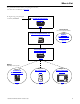
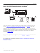
Where to Start Configurations for Quick Start This quick start demonstrates the use of this hardware and network configuration. Option 1: 1769-L23E Packaged Controller with an EtherNet/IP Network Workstation 1769-L23E-QBFC1 or 1769-L23E-QB1B I/O I/O CompactLogix L23E PanelView Plus 600 PV+ 600 Stratix 6000 Switch POINT I/O Modules PowerFlex 40 Component Class Drive An Ethernet switch other than the Stratix 6000 switch may be used. For this quick start, the Stratix 6000 switch is recommended.
Where to Start Option 2: 1769-L23-QBFC1B Packaged Controller with a Serial Network(1) Workstation CompactLogix L23 DeviceNet Network PanelView Plus 600 PV+ 600 PowerFlex 40 Component Class Drive 1606 Power Supply POINT I/O Modules This option shows an example DeviceNet network that could be configured by using the chapter, Optional - Configuration of the DeviceNet Network (on page 125).
Where to Start Notes: 8 Publication IASIMP-QS010B-EN-P - October 2009
Table of Contents Quick Start Preface About This Quick Start . . . . . . . . . . . . . . . . . . . . . . . . . . . . . . . . . . . . . 15 Required Software . . . . . . . . . . . . . . . . . . . . . . . . . . . . . . . . . . . . . . . . . 16 CompactLogix Packaged Controller Software Requirements . . . . 16 POINT I/O Modules and PowerFlex 40 Drive Software Requirements . . . . . . . . . . . . . . . . . . . . . . . . . . . . . . . . . . . . . . . . . . 16 PanelView Plus Terminal Software Requirements . . . .
Configure the Packaged Controller . . . . . . . . . . . . . . . . . . . . . . . . . . . . 57 Configure Embedded I/O. . . . . . . . . . . . . . . . . . . . . . . . . . . . . . . . . . . 58 Add Ladder Logic to Test the Embedded Outputs . . . . . . . . . . . . . . . 59 Set the Communication Path and Download to the Controller . . . . . 62 Additional Resources . . . . . . . . . . . . . . . . . . . . . . . . . . . . . . . . . . . . . . . 64 Chapter 4 Add POINT I/O Modules Before You Begin. . . . . . . . . . .
Create a New Application . . . . . . . . . . . . . . . . . . . . . . . . . . . . . . . . . . 102 Create an RSLinx Enterprise Configuration in FactoryTalk View ME Software . . . . . . . . . . . . . . . . . . . . . . . . . . . . . . . . . . . . . . . . . . . . . . . . 103 Create Device Shortcuts to the Controller . . . . . . . . . . . . . . . . . . . . . 105 Create the OB16_Light Indicator . . . . . . . . . . . . . . . . . . . . . . . . . . . . 110 Create a Push Button . . . . . . . . . . . . . . . . . . . .
User Manual Preface About This User Manual . . . . . . . . . . . . . . . . . . . . . . . . . . . . . . . . . . . 151 Additional Resources . . . . . . . . . . . . . . . . . . . . . . . . . . . . . . . . . . . 151 Chapter 1 Overview of the CompactLogix Packaged Controllers Features of the Packaged Controllers . . . . . . . . . . . . . . . . . . . . . . . . . 153 1769-L23E-QB1B Packaged Controller . . . . . . . . . . . . . . . . . . . . . . . 154 1769-L23E-QBFC1B Packaged Controller . . . . . . . . . . . .
Configure the DC Outputs . . . . . . . . . . . . . . . . . . . . . . . . . . . . . . 199 DC Output Tags . . . . . . . . . . . . . . . . . . . . . . . . . . . . . . . . . . . . . . 199 Analog I/O. . . . . . . . . . . . . . . . . . . . . . . . . . . . . . . . . . . . . . . . . . . . . . 200 Analog I/O Wiring Diagrams . . . . . . . . . . . . . . . . . . . . . . . . . . . . 200 Configure the Analog I/O . . . . . . . . . . . . . . . . . . . . . . . . . . . . . . 203 Analog I/O Tags . . . . . . . . . . . . . . .
Notes: 14 Publication IASIMP-QS010B-EN-P - October 2009
Preface About This Quick Start This quick start provides examples and procedures for the use of a CompactLogix packaged controller system. This publication also includes RSLogix 5000 programming software version 18 updates. The procedures cover many of the most common user tasks, such as: • connecting the controller to multiple devices (local and distributed I/O, a drive, and a PanelView Plus terminal).
5 Required Software Your software requirements depend upon the CompactLogix system components you are using. Use the sections below to determine the software required for your system components.
5 DeviceNet Network Software Requirements If you plan to use a DeviceNet network with your packaged controller, this software is required: • RSNetWorx for DeviceNet • DeviceNet Tag Generator (included with RSLogix 5000 programming software) Publication IASIMP-QS010B-EN-P - October 2009 17
5 This table lists the hardware used in this quick start. The hardware you need depends on the options and examples you choose to complete. Specific hardware requirements are listed at the beginning of each chapter. Parts List Hardware Used in This Quick Start Quantity Cat. No.
5 Hardware Used in This Quick Start Quantity Cat. No.
5 This manual uses the following conventions. Conventions Convention Meaning Example bold Bold text denotes menus, menu items, buttons, or options. Click OK. Check/uncheck Click to activate/deactivate a checkbox. Check the Open Module Properties checkbox. Click Click left mouse button once. (Assumes cursor is positioned on object or selection.) Click Browse. Courier font Type or enter text exactly as shown. Type cmd. Double-click Click left mouse button twice in quick succession.
5 Additional Resources Resource Description 1769 CompactLogix Controllers Selection Guide, publication 1769-SG001 Provides information and specifications for consideration when selecting CompactLogix controllers and software. 1769 Compact I/O Selection Guide, publication 1769-SG002 Provides information and specifications for consideration when selecting I/O modules for use with the CompactLogix system. It includes Compact I/O, POINT I/O, and FLEX I/O modules.
5 Notes: 22 Publication IASIMP-QS010B-EN-P - October 2009
Chapter 1 Assemble the CompactLogix Hardware In this chapter, you install your CompactLogix hardware packaged controller. Before You Begin Determine which of these networks and appropriate hardware to use: • For the EtherNet/IP network (option 1), use either the 1769-L23E-QB1B or 1769-L23E-QBFC1B controller. • For a serial connection (option 2), use the 1769-L23-QBFC1B controller. What You Need • CompactLogix packaged controller: 1769-L23E-QB1B, 1769-L23E-QBFC1B, or 1769-L23-QBFC1B.
Chapter 1 Assemble the CompactLogix Hardware Follow These Steps Complete the steps shown for your controller.
Assemble the CompactLogix Hardware Chapter 1 Connect the Battery to the Packaged Controller Battery 1. Remove the battery door and connect the battery to the controller. 2. Insert the battery into the slot on the battery door. 3. Close the battery door. Record the Ethernet Address (MAC) 1769-L23E controllers The Ethernet address (MAC) is found on a label near the power-supply wiring terminal. This is an example address.
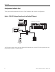
Chapter 1 Assemble the CompactLogix Hardware Make Network Connections 1769-L23E packaged controllers, option 1 1. Insert an Ethernet cable with an RJ45 connector. CompactLogix L23E 2. Connect the other end of the cable to the Ethernet switch. Ethernet Ports CompactLogix L23E QBFC-1B 1769-L23 packaged controllers, option 2 1. Connect the 1756-CP3 cable to the channel 0 serial port on the controller. 2. Connect the other end of the cable to a COM port on the computer.
Assemble the CompactLogix Hardware Chapter 1 Wire Power Power supply for all packaged controllers WARNING Verify that all incoming power is turned off before wiring power. 1. Insert the +24V DC, DC neutral, and ground wires and tighten the terminal screws. 2. Turn on incoming power.
Chapter 1 Assemble the CompactLogix Hardware Additional Resources Resource Description Chapter 6 of the user manual, page 237 Provides detailed information about the use of the 1769-BA with the packaged controllers. CompactLogix Packaged Controllers Installation Provides details about assembling and mounting the controller and upgrading firmware Instructions, publication 1769-IN082 as well as controller technical specifications.
Chapter 2 Prepare the Computer, Network, and Controller In this chapter, you configure network communication on your computer and install the necessary programming and configuration software. In this chapter, you also assign IP addresses to devices on an EtherNet/IP network. For more information about using the packaged controllers on an EtherNet/IP network, see Chapter 2 of the user manual, titled Network Communication (page 157).
Chapter 2 Prepare the Computer, Network, and Controller Follow These Steps Complete these steps. Serial EtherNet/IP Make Network Connections Make Network Connections page 31 page 31 Install RSLogix 5000 Programming Install RSLogix 5000 Programming page 33 page 33 Configure a Serial Driver Set the IP Address for the Computer page 38 page 40 Optional Install Additional Install additional software specific to your system.
Prepare the Computer, Network, and Controller Chapter 2 Terminology Ethernet networks use these types of addresses. Term Definition Ethernet Address Each Ethernet device has a unique Ethernet address (sometimes called a MAC address). The address appears as twelve digits separated by colons (for example, xx:xx:xx:xx:xx:xx). It is usually on a label on the device itself. Each digit is a number in hexadecimal (0 to 9 or A through F).
Chapter 2 Prepare the Computer, Network, and Controller Serial connection - Required for option 2 TIP If you are using an 1769-L23E packaged controller, you may choose to upgrade your controller firmware by using your Ethernet connection instead. If you use the Ethernet connection, you do not have to make this serial connection. Verify that you connected a 1756-CP3 cable to a COM port on the computer and to the CH0 port on the controller as described in Chapter 1.
Prepare the Computer, Network, and Controller Chapter 2 Install RSLogix 5000 Programming Software Required for all controllers Throughout the installation, click Next to use default RSLogix 5000 programming software installation settings except when indicated in the steps below. 1. Begin the RSLogix 5000 programming software installation. 2. Choose your language and click Continue. 3. Accept the default software products for installation and click Next. 4.
Chapter 2 Prepare the Computer, Network, and Controller 5. Accept the license agreement and click Next. 6. Click Next to install the program files to the default directory. 7. Select your activation type and click Next. This quick start uses FactoryTalk Activation software to activate RSLogix 5000 programming software. For more information, see the FactoryTalk Activation FAQ, publication FT00-FA001. 8. Click Next to install only the latest version of RSLogix 5000 programming software (version 17). 9.
Prepare the Computer, Network, and Controller Chapter 2 10. Click Next to install the typical firmware kits. 11. Click Next to install typical RSLogix Architect tools. 12. Click Next to install the typical set of EDS files and RSLinx software.
Chapter 2 Prepare the Computer, Network, and Controller 13. Click Install to complete the installation. The installation dialog box displays progress while the software installs. TIP As the installation progresses, you may be prompted to complete additional set-up tasks depending on your system configuration. Follow those prompts and enter information as indicated in the dialog boxes to complete your installation. After a few moments, the FactoryTalk Installation Wizard starts. 14. Click Next. 15.
Prepare the Computer, Network, and Controller Chapter 2 17. Select your host ID and click Next. The activation completes if the computer is connected to the Internet. If Internet access is not available, call Rockwell Automation Technical Support to complete your activation. 18. Click Finish to close the Activation Wizard.
Chapter 2 Prepare the Computer, Network, and Controller Configure a Serial Driver Required for serial network (option 2) 1. Launch RSLinx software. 2. From the Communications menu, choose Configure Drivers. 3. Select RS-232 DF1 devices. 4. Click Add New.
Prepare the Computer, Network, and Controller Chapter 2 6. Select the Comm Port to which you connected the 1756-CP3 cable. 7. From the Device pull-down, select Logix5550/CompactLogix. 8. Click Auto Configure. 9. Click OK. The Serial driver is added to the Configured Drivers list. 10. Verify that the Status of the driver is Running, and click Close. 11. Click the RSWho icon to view the driver. All of the configured, active drivers display. Expand the serial driver to see connected devices.
Chapter 2 Prepare the Computer, Network, and Controller Set the IP Address for the Computer Required for EtherNet/IP network (option1) 1. On your desktop, right-click My Network Places and choose Properties. 2. Double-click the Local Area Connection. 3. Click Properties. 4. On the General tab, select Internet Protocol (TCP/IP) and click Properties. 5. Select Use the following IP address and enter an IP address and Subnet mask for your computer. 6. Click OK.
Prepare the Computer, Network, and Controller Chapter 2 9. Click the Support tab. 10. Verify that the IP Address and Subnet Mask match what you entered on the Network Worksheet. If these numbers do not match what you entered, contact your network administrator to verify that your IP address is correct. 11. Close the Local Area Connection Status dialog box.
Chapter 2 Prepare the Computer, Network, and Controller Assign an IP Address to the Packaged Controller 1769-L23E packaged controllers In this chapter, you use the BOOTP/DHCP server to assign an IP address to the packaged controller. You use the BOOTP server that you installed with RSLogix 5000 software. TIP Devices on the EtherNet/IP network broadcast requests for IP addresses until the IP addresses have been assigned.
Prepare the Computer, Network, and Controller Chapter 2 The Request History displays all the devices, including the packaged controller, on your network that need an IP address. The Ethernet address (Mac ID) of the packaged controller corresponds with the address you recorded on Network Worksheet. 5. Double-click the request from your packaged controller. 6. Enter the IP address and record it on the Network Worksheet inside the back cover.
Chapter 2 Prepare the Computer, Network, and Controller Configure the EtherNet/IP Driver in RSLinx Software Required for EtherNet/IP network (option 1) 1. If RSLinx software is not open, launch RSLinx software. 2. From the Communications menu, choose Configure Drivers. 3. From the Available Driver Types, choose Ethernet/IP Driver. 4. Click Add New. 5. Click OK to keep the default name. 6. Click OK to Browse Local Subnet.
Prepare the Computer, Network, and Controller Chapter 2 The EtherNet/IP driver is added to the Configured Drivers list. 7. Verify that the driver’s Status is Running, and click Close. Browse the EtherNet/IP Network in RSLinx Software 1. In RSLinx Classic software, click the RSWho button. The EtherNet/IP driver and network devices display. 2. Expand the Ethernet Port and the backplane to view the packaged controller. 3. Close or minimize the RSLinx Classic window.
Chapter 2 Prepare the Computer, Network, and Controller Load Firmware Required for all packaged controllers 1. Launch ControlFlash software. 2. Click Next. 3. Select the controller catalog number and click Next.
Prepare the Computer, Network, and Controller Chapter 2 Ethernet 4. Expand the driver associated with your packaged controller. 5. Select your packaged controller. Packaged Controller Serial 6. Click OK. 7. Move the keyswitch on the controller to PROG. 8. If the Current Revision matches the revision of firmware you want, click Cancel and skip to Chapter 3. Otherwise, select the desired firmware revision and click Next.
Chapter 2 Prepare the Computer, Network, and Controller 9. Click Finish and then click Yes. 1769-L23E Only 10. If updating a 1769-L23E packaged controller, click OK after reading the release notes. The firmware upgrade begins. IMPORTANT Do not interupt the firmware upgrade once it has begun. Interrupting the firmware upgrade may result in an inoperable packaged controller. After the Upgrade Status dialog box indicates the upgrade is complete, you may proceed.
Prepare the Computer, Network, and Controller Chapter 2 During the firmware upgrade, these Progress dialog boxes display 2 or 3 times. Do not take any action while these status dialog boxes display. Status change. These status changes indicate that the Status change. packaged controller is self-cycling (Polling for power-up) and continuing with the firmware upgrade (Transmitting block). The Upgrade Status dialog box indicates that the firmware upgrade has been successfully completed. 11. Click OK. 12.
Chapter 2 Prepare the Computer, Network, and Controller Install Additional Software • If you are completing the PanelView Plus chapters in this quick start, install FactoryTalkView Machine Edition and RSLinx Enterprise software from the FactoryTalkView Machine Edition package. This software must be installed before you install any additional software. • If you are using a DeviceNet network, install RSNetWorx for DeviceNet software.
Prepare the Computer, Network, and Controller Chapter 2 Additional Resources Resource Description CompactLogix Packaged Controllers Installation Provides details about assembling and mounting the controller and upgrading firmware as well as controller technical specifications.
Chapter 2 Prepare the Computer, Network, and Controller Notes: 52 Publication IASIMP-QS010B-EN-P - October 2009
Chapter 3 Create a Project Using RSLogix 5000 Software In this chapter you create a project in RSLogix 5000 programming software. In the project you use ladder logic to create a push button that controls a light on a digital output of the controller. This project is used in subsequent chapters to test communication with other devices.
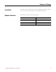
Chapter 3 Create a Project Using RSLogix 5000 Software Follow These Steps Complete these steps. Create a Project page 55 Configure the Packaged Controller page 57 Optional Not required to complete the examples in this quick start.
Create a Project Using RSLogix 5000 Software Chapter 3 Create a Project All controllers 1. Open RSLogix 5000 software by clicking Start > Programs > Rockwell Software > RSLogix 5000 Enterprise Series > RSLogix 5000. The Quick Start window displays in the RSLogix workspace. Navigation tabs for Quick Start, Learning Center, and Resource Center pages. The Quick Start pages provide useful links, tutorials, training videos, and other tools you may choose to view before beginning your project. 2.
Chapter 3 Create a Project Using RSLogix 5000 Software 1769-L23E-QB1B 1769-L23E-QBFC1B 3. Choose your controller and revision number. 4. Enter a unique controller name. 5. Click OK.
Create a Project Using RSLogix 5000 Software Chapter 3 Configure the Packaged Controller All 1769-L23E controllers 1. Right-click the Ethernet Port and choose Properties. 2. Enter the controller’s IP address (recorded on the Network Worksheet) and click OK.
Chapter 3 Create a Project Using RSLogix 5000 Software Configure Embedded I/O Not required for quick start examples The quick start examples use the default configuration of the embedded I/O. Before you use the embedded I/O in your application, you may choose to configure the embedded I/O specific to your application. 1. Double-click the embedded I/O you need to configure. 2. Use the tabs and boxes within the Module Properties dialog box to specify your configuration parameters.
Create a Project Using RSLogix 5000 Software Chapter 3 Add Ladder Logic to Test the Embedded Outputs All controllers 1. Expand the Tasks folders and double-click MainRoutine. A blank MainRoutine opens. 2. From the Element Toolbar, drag and drop an Examine On and an Output Energize element onto the rung.
Chapter 3 Create a Project Using RSLogix 5000 Software 3. Double-click the ? in the Examine On. 4. Type PB (for push button). 5. Press Enter. 6. Right-click PB and choose New ‘PB’. 7. Click OK to keep the defaults.
Create a Project Using RSLogix 5000 Software Chapter 3 8. Name the Output Energize Output_Light. IMPORTANT Do not use spaces in the tag name. Use underscores ( _ ) instead. 9. Right-click the Output_Light tag name and choose New ‘Output_Light’. Output_Light is an alias tag for the I/O point tag name. This lets you assign a simple name to a physical I/O point address. 10. From the Type pull-down menu, select Alias. 11. In the Alias For pull-down menu, browse to a local output point and select any bit.
Chapter 3 Create a Project Using RSLogix 5000 Software Set the Communication Path and Download to the Controller All 1769-L23 controllers 1. Save your changes. 2. Move the keyswitch on your controller to Program. 3. Click the RSWho button. EtherNet/IP 4. Expand the network tree. 5. Select your controller and click Set Project Path. 6. Click Download.
Create a Project Using RSLogix 5000 Software Chapter 3 7. Click Download. The project Path updates. EtherNet/IP Serial 8. Move the keyswitch on your controller to Run. 9. Select the PB Examine On instruction and press Ctrl+T. This toggles the state from 0 to 1 (off to on). Off On 10. Verify that the LED indicator on the digital output of the controller turns on. 11. Press Ctrl+T to toggle the state back to 0 (off). 12. Go Offline.
Chapter 3 Create a Project Using RSLogix 5000 Software Additional Resources Resource Description Chapter 5 of the user manual, Program the Packaged Controller, on page 233 Provides detail information about programming the packaged controllers, including available user memory, available programming languages, use of programs and equipment phases, and monitoring controller status.
Chapter 4 Add POINT I/O In this chapter, you install the 1734 POINT I/O network adapter and the 1734 POINT I/O modules. You then add POINT I/O modules to your project using RSLogix 5000 programming software. You also add ladder logic and download the project to the controller so you can test communication with an I/O module. This project builds upon the program created in Chapter 3. Before You Begin • Create a project in RSLogix 5000 programming software, see Chapter 3.
Chapter 4 Add POINT I/O Follow These Steps If you are using POINT I/O modules, complete these steps.
Add POINT I/O Chapter 4 Mount and Connect the Network Adapter EtherNet/IP network 1. Locate the Ethernet address (MAC), found next to the label. Record the Ethernet address (MAC) for the POINT I/O adapter on the Network Worksheet. Example Address (Found on the right side of the module.) 00:00:BC:21:8A:B6 Ethernet Address This address is used to set the IP address later in the quick start. 2. Set the address to a value greater than or equal to 256. This example uses 999. 3. Remove the safety end cap. 4.
Chapter 4 Add POINT I/O Mount the POINT I/O Modules All controllers, POINT I/O modules, and wiring bases IMPORTANT The 1734-IT2I module must be mounted in the 1734-TBCJC wiring base. All other modules can be mounted in either of the 1734-TB or 1734-TBS wiring bases. 1. Using a small, flathead screwdriver, rotate the keyswitch to match the figure on the I/O module. Wiring Base Figure on Module 2. Press the module into the wiring base. Module 3. Snap the handle up. 4.
Add POINT I/O Chapter 4 Mount and Wire the POINT I/O Power Supply 1794-PS3 or 1794-PS13 power supplies TIP You can choose to power your POINT I/O with the listed POINT I/O power supplies, or, use the DC power supply powering your packaged controller. Any 24V DC power supply can be used with the POINT I/O. Verify that any power supply you use is disconnected before wiring power. 1. Hook the upper-lip of the DIN rail latch onto the DIN rail. Upper-lip of DIN-rail latch. 2.
Chapter 4 Add POINT I/O Wire the Adapter and I/O Modules to the Power Supply POINT I/O adapter, I/O modules, and power supply 1. Connect the 12/24V DC common and 12/24V DC power wires from the power supply to the adapter. 2. Refer to the individual POINT I/O installation instructions for wiring the I/O modules. 3. Turn on incoming power.
Add POINT I/O Chapter 4 Assign an IP Address to the POINT I/O Adapter EtherNet/IP network In this chapter, you use the BOOTP/DHCP server to assign an IP address to the POINT I/O adapter. You use the BootP server that was installed with RSLogix 5000 programming software. TIP Devices on the EtherNet/IP network broadcast requests for IP addresses until the IP addresses have been assigned.
Chapter 4 Add POINT I/O The Request History displays all the devices, including the packaged controller, on your network that need an IP address. The Ethernet address (MAC ID) of the adapter corresponds with the address you recorded on Network Worksheet. 5. Double-click the request from your adapter. 6. Enter the IP address and record it on the Network Worksheet inside the back cover. If you are not using an isolated network, obtain these numbers from your network administrator.
Add POINT I/O Chapter 4 Add POINT I/O Modules to the Project 1. Verify that your project is Offline. 2. Right-click the network port and choose New Module. 3. Select the 1734-AENT POINT I/O network adap and click OK. 4. Specify the major revision and click OK. Module Properties dialog box opens.
Chapter 4 Add POINT I/O 5. Type a name for the adapter. 6. Type the IP address. Use the Network Worksheet located inside the back cover as a reference. 7. Select the Chassis Size (exact number of POINT I/O modules + 1 for the adapter). 8. Verify that Open Module Properties is unchecked and click OK. The adapter is added to the I/O configuration. 9. Right-click the 1734 POINT network adapter module and choose New Module.
Add POINT I/O Chapter 4 10. Select the left-most POINT I/O module in your chassis and click OK. 11. Enter a name. 12. Click OK. The module is added to the I/O Configuration. Completed Configuration of POINT I/O Modules 13. Repeat steps 9…12 until all of your POINT I/O modules are added in order from left to right. After you have completed adding your POINT I/O modules, go to Add Ladder Logic on page 76.
Chapter 4 Add POINT I/O Add Ladder Logic 1. In the Main Routine, drag and drop a Branch onto the rung. 2. Expand the branch to the right side of Output _Light. 3. Drag and drop another Output Energize element onto the Branch and name it xxxx_Light (where xxxx identifies your output module).
Add POINT I/O Chapter 4 4. Right-click the Light and choose New ‘xxxx_Light’. 5. From the Type pull-down, choose Alias. 6. From the Alias For pull-down menu, browse to find your 1734 output module. 7. Click the output point you want to use. 8. Click OK. 9. Click Save.
Chapter 4 Add POINT I/O Download the Project 1. Move the keyswitch on your controller to Program. 2. Click the Controller Status icon and choose Download. 3. Click Download. If you have no loads wired to your output modules, the red status LEDs indicators may start blinking. If you are using an EtherNet/IP network, after you download to the controller, the 1734 modules may show faults. Setting the chassis size as shown in the next section should resolve these faults.
Add POINT I/O Chapter 4 Set the POINT I/O Chassis Size 1. Right-click the 1734-AENT and choose Properties. 2. Click the Chassis Size tab. If the both the chassis sizes match, skip to step 1 on page 80. If the numbers do not match, continue with step 3. 3. On the Connection tab, check the Inhibit Module checkbox and click Apply. 4. Click Yes. 5. On the Chassis size tab, click Set Chassis Size in Module. 6. Click OK at the warning. The Module chassis size updates. 7.
Chapter 4 Add POINT I/O Test the POINT I/O Light 1. Move the keyswitch on your controller to RUN. 2. Select the PB and press Ctrl+T. This toggles the state from 0 to 1 (off to on). Off On 3. Verify that the lights on both the embedded and POINT digital output modules turn on. 4. Press Ctrl+T to toggle the state back to 0 (off). 5. Choose Go Offline.
Add POINT I/O Chapter 4 Additional Resources Resource Description Point I/O Ethernet Adapter Installation Instructions, publication 1734-IN590 Provides details regarding installation of the adapter and technical specifications. 1734 Point I/O ControlNet Adapter Installation Instructions, publication 1734-IN582 Provides details regarding installation of the adapter and technical specifications.
Chapter 4 Add POINT I/O Notes: 82 Publication IASIMP-QS010B-EN-P - October 2009
Chapter 5 Add a PowerFlex 40 Drive In this chapter, you mount and wire power to a PowerFlex 40 drive, configure your communication adapter, and make network connections. You then configure a PowerFlex 40 drive using the drive keypad and add the drive to your project using RSLogix 5000 programming software. This project builds upon the project created in Chapter 3. Before You Begin • Create a project using RSLogix 5000 programming software, see Chapter 3.
Chapter 5 Add a PowerFlex 40 Drive Follow These Steps If you have a PowerFlex 40 drive, complete these steps for your network.
Add a PowerFlex 40 Drive Chapter 5 Mount the PowerFlex 40 Drive For this quick start, the PowerFlex 40 drive is simply placed on a desktop. For complete mounting instructions, see the PowerFlex 40 Drive User Manual, publication 22B-UM001. Wire Power WARNING Verify that all incoming power is turned off before wiring power. 1. Remove the cover. 2. Remove the terminal block cover to access the power connections. 3. Insert the 120/240V AC, V AC COM and chassis ground wires and tighten the terminal screws.
Chapter 5 Add a PowerFlex 40 Drive Connect the Communication Adapter 1. Attach the extending screws. 1. Record the Ethernet address (MAC ID) of the Ethernet adapter on the Network Worksheet. The Ethernet address is found on the label on the back of the Ethernet adapter. 0.8…1 Nm (7…9 lb-in) Ethernet Adapter Label Allen-Bradley 22 -CO MM- E SERIES A FRN: V1.003 SN: 40018FB6 DEVICE: 5vDC 350mA HW ADDRESS: 00:00:BC:08:85:B6 2.
Add a PowerFlex 40 Drive Chapter 5 3. Place the adapter cover on the PowerFlex drive. 4. Tighten the screws. 5. Connect the network cable to the adapter. 6. Apply power to the PowerFlex 40 drive. 0.5…0.6 Nm (4…5 lb-in) 0.5-0.6 N-m (4-5 lb.-in.
Chapter 5 Add a PowerFlex 40 Drive Assign an IP Address to the PowerFlex 40 Drive EtherNet/IP network In this chapter, you use the BOOTP/DHCP server to assign an IP address to the PowerFlex 40 drive. You use the BootP server that was installed with RSLogix 5000 programming software. TIP Devices on the EtherNet/IP network broadcast requests for IP addresses until the IP addresses have been assigned.
Add a PowerFlex 40 Drive Chapter 5 The Request History displays all the devices, including the drive, on your network that need an IP address. The Ethernet address (MAC ID) of the drive corresponds with the address you recorded on Network Worksheet. 5. Double-click the request from your adapter. 6. Enter the IP address and record it on the Network Worksheet inside the back cover. If you are not using an isolated network, obtain these numbers from your network administrator.
Chapter 5 Add a PowerFlex 40 Drive Add the Drive to the Project 1. Verify that you are not online with the packaged controller. 2. Right-click your network port and choose New Module. 3. Expand Drives. 4. Select the PowerFlex 40-E. 5. Click OK. 6. In the Name box, type a name for the drive. 7. Enter the IP Address for your drive. Use the Network Worksheet as a reference. 8. Click Change.
Add a PowerFlex 40 Drive Chapter 5 9. From the Electronic Keying pull-down menu, select Disable Keying. 10. Click OK. 11. Click OK again. The PowerFlex 40 drive is added to the controller organizer.
Chapter 5 Add a PowerFlex 40 Drive Download the Project TIP If you receive a fault message on your PowerFlex 40 drive, press keypad to clear the fault. on the 1. If you have not already done so, move the keyswitch on your controller to PROG. 2. Click the Controller Status icon and choose Download. 3. Click Download. The project downloads to the controller.
Add a PowerFlex 40 Drive Chapter 5 Edit PowerFlex 40 Parameter Values TIP Use the table below as a reference when editing parameter values as instructed on page 94. When power is first applied to the PowerFlex 40 drive, the display defaults to the current value. Reference for Editing Parameters Step Displayed 1. Press . The parameter number is displayed and blinks. 2. Press to select the group letter. The group letter blinks. 3.
Chapter 5 Add a PowerFlex 40 Drive Use the reference on page 93 to make the following parameter value edits on your PowerFlex 40 drive. 1. If your PowerFlex 40 drive has been previously used, reset it to factory defaults. a. Change the value of parameter P041 from 0 to 1. The drive is reset and fault F048 is displayed and blinks. b. Press c. Press to clear the fault. to return to editing parameters. 2. Change the value of parameters P036 and P038 from 0 to 5.
Add a PowerFlex 40 Drive Chapter 5 Test the PowerFlex 40 Tags TIP To change a tag in RSLogix 5000 software: 1. Select the tag value. 2. Enter or select the desired value. 3. Press . 1. Move the controller keyswitch to RUN. 2. Double-click Controller Tags. 3. Expand the PowerFlex 40 output tag. 4. At the O.FreqCommand Tag, enter 555. The value 555 equals 55.5 Hz.
Chapter 5 Add a PowerFlex 40 Drive 4. At the O.Start tag, enter 1. The drive begins to run and the display registers the drive’s speed until it reaches 55.5 Hz. 5. After the drive has reached 55.5 Hz, enter 0 at the O.Start tag. 6. At the O.Stop tag, enter 1. The drive begins to slow until reaching 0.0 Hz. 7. When the drive reaches 0.0 Hz, enter 0 at the O.Stop tag. 8. Go Offline. By starting and stopping the drive, you verified that: • the controller is correctly communicating with the drive.
Chapter 6 Add a PanelView Plus 600 Terminal In this chapter, you mount and wire power to a PanelView Plus terminal, configure network communication, and make network connections. You also use RSView software to create indicators to represent the push button and output you created in Chapter 3. You transfer the application to the PanelView Plus terminal so you can test communication with the controller. Before You Begin • Create a project in RSLogix 5000 programming software, see Chapter 3.
Chapter 6 Add a PanelView Plus 600 Terminal Follow These Steps If you have a PanelView Plus terminal, complete these steps.
Add a PanelView Plus 600 Terminal Chapter 6 Mount the PanelView Plus Terminal 2711P-K10C4D1 terminal and all packaged controllers For the purpose of this quick start, the PanelView Plus terminal can be propped on a desktop. For further mounting instructions, see the PanelView Plus Terminals User Manual, publication 2711P-UM001. Wire the PanelView Plus Terminal for Power WARNING Verify that all incoming power is turned off before wiring power.
Chapter 6 Add a PanelView Plus 600 Terminal Make Network Connections Required for all controllers Serial cable connection (from 1769-L23-QBFC1B serial port). Ethernet cable connection.
Add a PanelView Plus 600 Terminal Chapter 6 Assign an IP Address to the Terminal Required for all controllers 1. On the PanelView Plus terminal’s main page, press Terminal Settings [F4]. 2. Navigate to: Networks and Communications > Network Connection > Network Adaptors > Built-in Ethernet Controller. 3. Press IP Address [F2]. 4. Press IP Address [F1] and enter an IP address. For more information about IP addresses, see Chapter 2, on page 97. 5.
Chapter 6 Add a PanelView Plus 600 Terminal Create a New Application All controllers 1. Launch Factory Talk View Studio software. FactoryTalk View software opens. 2. In the Application name box, type a name and click Create. Do not use spaces in the tag name. Use underscores ( _ ) instead.
Add a PanelView Plus 600 Terminal Chapter 6 Create an RSLinx Enterprise Configuration in FactoryTalk View ME Software All controllers 1. In the organization tree, expand RSLinx Enterprise and double-click Communication Setup. 2. Click Finish. RSLinx Enterprise opens.
Chapter 6 Add a PanelView Plus 600 Terminal About the Design(Local) and Runtime(Target) Paths • The Design(Local) tab defines the path from the computer to the controller. The local path is the communication path used when in Test Run mode and when browsing tags during online application of an HMI display. • The Runtime(Target) tab defines the path from the PanelView Plus terminal to the controller.
Add a PanelView Plus 600 Terminal Chapter 6 Create Device Shortcuts to the Controller 1769-L23E packaged controllers (for a 1769-L23 controller, skip to page 107) 1. Click Add and type a shortcut name. 2. Select the newly-named shortcut. 3. In the Design(Local) tab, browse to and select your controller. 4. Click Apply. The shortcut to the controller is now created. 5. Click Yes.
Chapter 6 Add a PanelView Plus 600 Terminal 6. With the shortcut highlighted, click Copy from Design to Runtime. 7. Click Yes. 8. Click the Runtime(Target) tab to view the path from the PanelView Plus terminal to the controller. 9. Verify that the shortcut path in this Runtime(Target) tab is the same as the shortcut path specified in the Design(Local) tab. Go to Create the OB16_Light Indicator on page 110.
Add a PanelView Plus 600 Terminal Chapter 6 1769-L23 controller (to complete this step on the 1769-L23E controllers, see page 105;) IMPORTANT Before you add the Serial driver in the following steps, you must stop and delete the Serial driver in RSLinx Classic. Depending on the messages that display, you might have to take all programming and configuration software offline. To do so, from the RSLinx Classic File menu, choose Exit and Shutdown.
Chapter 6 Add a PanelView Plus 600 Terminal 6. Below Device Shortcuts, click Add. 7. Type a shortcut name. 8. Select the newly-named shortcut. 9. In the Design(Local) tab, browse to and select your controller. 10. Click Apply. The shortcut to the controller is now created.
Add a PanelView Plus 600 Terminal Chapter 6 11. With the shortcut highlighted, click Copy from Design to Runtime. 12. Click Yes. 13. Click the Runtime(Target) tab to view the path from the PanelView Plus terminal to the controller. 14. Verify that the shortcut path in this Runtime(Target) tab is the same as the shortcut path specified in the Design(Local) tab. Go to Create the OB16_Light Indicator on page 110.
Chapter 6 Add a PanelView Plus 600 Terminal Create the OB16_Light Indicator All controllers 1. In FactoryTalk View organization tree, expand Graphics. 2. Right-click Displays and choose New. 3. From the Objects, choose Indicator > Multistate. 4. Click and drag in the display window to create the indicator. 5. Right-click the indicator and choose Properties.
Add a PanelView Plus 600 Terminal Chapter 6 6. On the General tab, in Number of states pull-down choose 2. 7. On the States tab, verify that State0 is selected. 8. In the Caption, type Light is OFF. 9. Select State1. 10. In the Caption, type Light is ON. 11. Change the Back color to green. 12. Change the Caption color to black.
Chapter 6 Add a PanelView Plus 600 Terminal 13. On the Connections tab, click ... under Tag. 14. Right click your project and choose Refresh All Folders. 17. Expand the controller shortcut and select Online > Program: Main Program. 18. Select Output_Light (the name of your output used in ladder logic) and click OK. The Indicator tag is populated. 19. Click OK.
Add a PanelView Plus 600 Terminal Chapter 6 Create a Push Button All controllers 1. From the Objects menu, choose Push Button > Maintained. 2. Click and drag to create the push button beneath the indicator. 3. Right-click the push button you just created and choose Properties. 4. On the States tab, verify that State0 is selected. 5. In the Caption, type Push to turn light ON. 6. Select State1. 7. In the Caption, type Push to turn light OFF.
Chapter 6 Add a PanelView Plus 600 Terminal 8. Click the Connections tab. 9. In the Value row, click ... under Tag. 10. Expand your controller shortcut and choose Online > Program; MainProgram. 11. Select PB and click OK. The Value tag is populated. 12. Click OK to close the properties dialog box.
Add a PanelView Plus 600 Terminal Chapter 6 Test the Indicator and Push Button All controllers 1. Verify that the keyswitch on your controller is moved to Run. 2. Right-click an unused area of the display and select Display Settings. 3. Change the Maximum Tag Update Rate to 0.05. 4. Click OK and then click OK again. 5. Click the Play button.
Chapter 6 Add a PanelView Plus 600 Terminal 6. Click the Push Button to toggle the state and turn the light on and off. You can also view the connected logic in the Main Program of the project you created in Chapter 3. 7. Click the Stop button. 8. Save your changes. When prompted for a title for the display, type test_logic.
Add a PanelView Plus 600 Terminal Chapter 6 Add a Goto Configuration Mode Button All controllers 1. From the Objects menu, choose Advanced > Goto Configure Mode. 2. In the Display window, click and drag to create the Goto button. 3. Right-click the new pushbutton and select Properties. 4. On the Label tab, enter Goto Config for the caption. Goto Configuration Button Complete 5. Click OK.
Chapter 6 Add a PanelView Plus 600 Terminal Assign Keys All controllers with PanelView Plus terminals without a touchscreen If your PanelView Plus does not have a touch screen, you must assign functions keys to the display buttons. If your PanelView Plus has a touchscreen, skip to page 120. 1. Right-click the Push Button and choose Key Assignments. 2. In the Select an object list, verify that MaintainedPushButton is selected. 3. Select a function key and click Apply. This example uses F2. 4.
Add a PanelView Plus 600 Terminal Chapter 6 7. Add the function key names to the button captions (including both states of the indicator). Add the function key names by using the State tab of the button’s Properties dialog box to add the text (for example, [F2]) to the Caption box. 8. Save your changes.
Chapter 6 Add a PanelView Plus 600 Terminal Assign an Initial Screen All controllers 1. Under System, double-click Startup. 2. Check the Initial graphic checkbox and select test_logic. 3. Click OK. 4. Save your changes.
Add a PanelView Plus 600 Terminal Chapter 6 Transfer to the PanelView Plus Terminal All controllers 1. Under Application, choose Create Runtime Application. 2. In Save as type, select the Runtime version that matches your PanelView Plus firmware. TIP To check the PanelView Plus firmware revision, on the terminal select Terminal Setting [F4] > System Information > About FactoryTalkViewME Station. 3. Click Save to accept the default file name. 4. From the Tools menu, choose Transfer Utility. 5.
Chapter 6 Add a PanelView Plus 600 Terminal 6. Verify that the Replace communications checkbox is checked and verify that your PanelView Plus is selected for the destination terminal. Check Select. 7. Click Download. 8. Click OK. After the download is complete, your PanelView Plus terminal may restart. After the restart, the application file you specified is loaded.
Add a PanelView Plus 600 Terminal Chapter 6 Test the Application on the PanelView Plus Terminal All controllers 1. On the PanelView Plus, press Load Application [F1]. 2. Select your .mer file and press Run Application [F2]. 3. Press Yes [F7]. 4. After the application loads, press Run Application [F2]. 5. Press the Push Button. Verify that the indicator turns on and that the light on the Compact digital output module turns on. 6.
Chapter 6 Add a PanelView Plus 600 Terminal Additional Resources Resource Description FactoryTalk View online help Contains procedures and information for all RSView-specific topics. PanelView Plus Terminal User Manual, publication 2711p-UM001 Provides descriptions and procedures for the use of the PanelView Plus terminal.
Chapter 7 Optional - Configuration of the DeviceNet Network This chapter describes some of the tasks required to set-up and configure a DeviceNet network with your packaged controller. IMPORTANT This chapter does not provide complete details for the installation and configuration of a DeviceNet network.
Chapter 7 Optional - Configuration of the DeviceNet Network Follow These Steps If you are using a DeviceNet network, you may need to complete these tasks.
Optional - Configuration of the DeviceNet Network Chapter 7 Attach the 1769-SDN Module to the Packaged Controller Unlocked 1. On the top of the 1769-SDN module, verify that the locking tab is unlocked. Locked 2. Use the tongue-and-groove slots to slide the 1769-SDN onto the end of the controller. 3. Lock the locking tabs. 4. Record the series letter from the 1769-SDN module label on the Network Worksheet inside the back cover of this quick start.
Chapter 7 Optional - Configuration of the DeviceNet Network Connect the 1769-SDN Module to the Network A DeviceNet network requires a power supply (see Connect and Apply Power to the DeviceNet Network on page 129) and a terminated network. For further details on DeviceNet networks, see the DeviceNet Media Design and Installation Guide, publication DNET-UM072. 1. Connect a DeviceNet cable to the removable connector. Connect To Red V+ White CAN High Bare Shield Blue CAN Low Black V- 2.
Optional - Configuration of the DeviceNet Network Chapter 7 Connect and Apply Power to the DeviceNet Network 1606-XLDNET8 power supply WARNING Verify that all incoming power is turned off before wiring power. 1. Connect incoming power to the power supply. Connect To V AC COM N (neutral) 120/240V AC L (line) 1606POWE XL R SUP PLY AC 120 V AC 240 V Ground 2. Place the switch in the position that matches your supply voltage.
Chapter 7 Optional - Configuration of the DeviceNet Network Set the 1769-SDN Module’s Node Address 1. Launch RSNetWorx for DeviceNet software. 2. From the Tools menu, choose Node Commissioning. 3. Click Browse. 4. Expand to the CompactLogix Backplane and the 1769 Bus. Depending on your system, you might choose browse to the 1769-SDN via the EtherNet/IP network. 5. Expand the 1769-SDN and the DeviceNet Port, and select the 1769-SDN. 6. Click OK.
Optional - Configuration of the DeviceNet Network Chapter 7 7. If you receive a linking device warning, click Yes. The Node Commissioning dialog box is populated with the 1769-SDN module’s current settings. 8. Select an available node Address for the 1769-SDN module and click Apply. This example uses node address 1. The node address is applied and a confirmation is given in the Messages box. TIP If you receive an communication error, verify that the scanner is not running.
Chapter 7 Optional - Configuration of the DeviceNet Network Create a DeviceNet Scanlist Required with the use of any DeviceNet device This procedure is required if you use any devices on the DeviceNet network - you must create a scanlist that includes all of the DeviceNet devices in your network. The examples in this section use a 1734-ADNX adapter that is has already been configured. 1. Select Network > Upload from Network. 2. Right-click the 1734-ADNX adapter and select Properties. 3.
Optional - Configuration of the DeviceNet Network Chapter 7 5. Right-click the 1769-SDN module and select Properties. 6. Click the Scanlist tab. 7. Click Upload. The configuration is uploaded from the device. 8. Select the 1734-ADNX adapter and move it to the Scanlist. 9. Click Edit I/O Parameters.
Chapter 7 Optional - Configuration of the DeviceNet Network 10. Verify that the I/O parameters match those verified at step 3. If these parameters do not match those at step 3, check your adapter and output module configurations. Depending on the POINT output module you use, these parameters may be different than those shown here. 11. Click OK. 12. Verify that Automap on Add is checked and click Apply. 13. Click Yes. 14. Save the configuration file. 15. Close RSNetworx for DeviceNet software.
Optional - Configuration of the DeviceNet Network Chapter 7 Create a DeviceNet Configuration File This example shows the steps required create a DeviceNet configuration file using a network that has already been configured. If you are starting with a network that has not been configured, the steps are the same, however, the network will appear differently than shown here. 1. Open RSNetWorx for DeviceNet software. 2. From the File menu, select New. 3. Select DeviceNet Configuration and click OK. 4.
Chapter 7 Optional - Configuration of the DeviceNet Network 9. Click OK. RSNetWorx software begins browsing the network. TIP Once all of the devices on your DeviceNet network appear, you can click Cancel. If a question mark displays instead of the PowerFlex drive, see Uploading an EDS File From a Drive, Knowledgebase ID 20539. 10. Right-click the 1769-SDN module and choose Properties. 11. Click the Module tab. 12. Click Download.
Optional - Configuration of the DeviceNet Network Chapter 7 13. From the Platform pull-down menu, select CompactLogix. 14. Enter the slot number of the 1769-SDN you recorded on the Network Worksheet. 15. Click OK. 16. Save the file and record the file name and path on the Network Worksheet. This quick start uses the example file name MainDNet_L2x.dnt. 17. Close RSNetWorx for DeviceNet software.
Chapter 7 Optional - Configuration of the DeviceNet Network Add the 1769-SDN Module to the RSLogix 5000 Project 1. In the RSLogix 5000 configuration tree, right-click CompactBus Local and select New Module. 2. Under Communications, select 1769-SDN with the series letter recorded on the Network Worksheet and click OK. 3. In the Name box, type a name for your SDN module. 4. In the Slot box, type or choose the Slot number. The slot number you specify depends on which 1769-L23 controller you use. 5.
Optional - Configuration of the DeviceNet Network Chapter 7 8. On the RSNetWorx tab, click Browse to find the configuration (.dnt) file recorded on the Network Worksheet. Use the configuration file name you saved on page 137. This quick start uses MainDNet_L2x.dnt. 9. Click OK. The module is added to the I/O Configuration.
Chapter 7 Optional - Configuration of the DeviceNet Network Create DeviceNet Tags Recommended for any DeviceNet device Complete these steps after you have configured your DeviceNet network and devices and are ready to begin programming. IMPORTANT Before running the DeviceNet Tag Generator, verify that RSNetWorx for DeviceNet software is closed. 1. In RSLogix 5000 programming software, from the Tools menu, choose DeviceNet Tag Generator. 2. Select your RSLogix 5000 project. 3. Click Select Scanner. 4.
Optional - Configuration of the DeviceNet Network Chapter 7 8. Select the node of the 1769-SDN scanner as recorded on the Network Worksheet. 9. Click Generate Tags. 10. Click Generate Tags. 11. Click Yes. When tag generation is complete, the text log displays. 12. Close the DeviceNet Tag Generator. Note that new programs and tags have been added to the controller organizer. These tasks were created by the Tag Generator.
Chapter 7 Optional - Configuration of the DeviceNet Network Additional Resources Resource Description 1769-SDN Compact I/O DeviceNet Scanner Module Installation Instructions, publication 1769-IN060 Provides information about installing the 1769-SDN module and technical specifications. DeviceNet Modules in Logix5000 Control Systems, publication DNET-UM004 Provides details regarding the installation, configuration, and operation of DeviceNet modules.
1769 CompactLogix Packaged Controllers Catalog Numbers 1769-L23E-QB1B, 1679-L23E-QBFC1B, and 1769-L23-QBFC1B User Manual
Important User Information Solid state equipment has operational characteristics differing from those of electromechanical equipment. Safety Guidelines for the Application, Installation and Maintenance of Solid State Controls (publication SGI-1.1 available from your local Rockwell Automation sales office or online at http://www.rockwellautomation.com/literature/) describes some important differences between solid state equipment and hard-wired electromechanical devices.
Table of Contents User Manual Preface About This User Manual . . . . . . . . . . . . . . . . . . . . . . . . . . . . . . . . . . . 151 Additional Resources . . . . . . . . . . . . . . . . . . . . . . . . . . . . . . . . . . . 151 Chapter 1 Overview of the CompactLogix Packaged Controllers Features of the Packaged Controllers . . . . . . . . . . . . . . . . . . . . . . . . . 153 1769-L23E-QB1B Packaged Controller . . . . . . . . . . . . . . . . . . . . . . . 154 1769-L23E-QBFC1B Packaged Controller . . .
DC Output Wiring. . . . . . . . . . . . . . . . . . . . . . . . . . . . . . . . . . . . . 198 Configure the DC Outputs . . . . . . . . . . . . . . . . . . . . . . . . . . . . . . 199 DC Output Tags . . . . . . . . . . . . . . . . . . . . . . . . . . . . . . . . . . . . . . 199 Analog I/O. . . . . . . . . . . . . . . . . . . . . . . . . . . . . . . . . . . . . . . . . . . . . . 200 Analog I/O Wiring Diagrams . . . . . . . . . . . . . . . . . . . . . . . . . . . . 200 Configure the Analog I/O . . . . . . . .
Notes: Publication IASIMP-QS010B-EN-P - October 2009 147
Notes: 148 Publication IASIMP-QS010B-EN-P - October 2009
Notes: Publication IASIMP-QS010B-EN-P - October 2009 149
Notes: 150 Publication IASIMP-QS010B-EN-P - October 2009
Preface About This User Manual Use this manual to become familiar with the CompactLogix packaged controllers’ hardware and corresponding RSLogix 5000 programming software features. This user manual is written for use with the quick start provided at the front of this publication.
10 Preface Notes: 152 Publication IASIMP-QS010B-EN-P - October 2009
Chapter 1 Overview of the CompactLogix Packaged Controllers Features of the Packaged Controllers Topic Page Features of the Packaged Controllers 153 1769-L23E-QB1B Packaged Controller 154 1769-L23E-QBFC1B Packaged Controller 154 1769-L23-QBFC1B Packaged Controller 155 The CompactLogix packaged controllers provide a complete system solution for small applications by providing these features: • Configurable embedded I/O • Capacity for expansion I/O • Isolated serial connection • Built-in Etherne
Chapter 1 Overview of the CompactLogix Packaged Controllers 1769-L23E-QB1B Packaged Controller The 1769-L23E-QB1B packaged controller has these hardware features. Controller Status Indicators 16 Digital Inputs 16 Digital Outputs CompactLogix L23E Ethernet Port 9-pin Isolated Serial Port 1769-L23E-QBFC1B Packaged Controller The 1769-L23E-QBFC1B packaged controller has these hardware features.
Overview of the CompactLogix Packaged Controllers 1769-L23-QBFC1B Packaged Controller Chapter 1 The 1769-L23-QBFC1B packaged controller has these hardware features.
Chapter 1 Overview of the CompactLogix Packaged Controllers Notes: 156 Publication IASIMP-QS010B-EN-P - October 2009
Chapter 2 Network Communication Topic Page EtherNet/IP Network Communication 158 Software for an EtherNet/IP Network 158 EtherNet/IP Network Features 159 EtherNet/IP Network Connections 159 Packaged Controllers, EtherNet/IP Connections, and RPI 159 Maximum Ethernet Interface Connections 160 Configure the 1769-L23E Ethernet Interface 161 Additional Resources for EtherNet/IP Networks 163 DeviceNet Network Communication CompactLogix DeviceNet Scanner 164 Software for a DeviceNet Network
Chapter 2 Network Communication EtherNet/IP Network Communication The EtherNet/IP network offers a full suite of control, configuration, and data collection services by layering the Common Industrial Protocol (CIP) over the standard Internet protocols, such as TCP/IP and UDP. This combination of well-accepted standards provides the capability required to both support information data exchange and control applications.
Network Communication Chapter 2 EtherNet/IP Network Features When used with the CompactLogix packaged controller, the EtherNet/IP communication network provides these features: • Supports messaging, produced/consumed tags, HMI, and distributed I/O • Encapsulation of messages within standard TCP/UDP/IP protocol • Use of a shared application layer with the DeviceNet network • Easily interfaces via RJ45, category 5, unshielded, twisted-pair cable • Supports half/full-duplex 10 Mbps or 100 Mbps operation • Su
Chapter 2 Network Communication Use this table as a reference when determining how to configure your Ethernet network RPI. Ethernet Interface Connections According to RPI Requested Packet Interval Ethernet Interface Connections, max 2 ms 2 4 ms 5 8 ms 10 16 ms 18 32 ms+ 25+ We recommend that you leave some connections available for tasks, such as going online and non-I/O purposes.
Network Communication Chapter 2 Configure the 1769-L23E Ethernet Interface You may choose to configure your packaged controller’s Ethernet interface by using a BOOTP server as shown in Chapter 2 of the quick start (page 29) or by using RSLogix 5000 software. To configure your 1769-L23E packaged controller Ethernet interface in RSLogix 5000 software, right-click the Ethernet port and choose Properties.
Chapter 2 Network Communication Use the Properties dialog box that displays to specify the Ethernet interface configuration.
Network Communication Chapter 2 Additional Resources for EtherNet/IP Networks Resource Description Prepare the Computer, Network, and Controller, page 29 of the quick start in this publication This chapter describes how to assign an IP address to an Ethernet module and shows how the Ethernet networks appear in RSLinx software. EtherNet/IP Modules in Logix5000 Control Systems User Manual, publication ENET-UM001 This manual describes how you can use EtherNet/IP modules with your Logix controller.
Chapter 2 Network Communication DeviceNet Network Communication The DeviceNet network uses the Common Industrial Protocol (CIP) to provide the control, configuration, and data collection capabilities for industrial devices. The DeviceNet network uses the proven Controller Area Network (CAN) technology, which lowers installation costs and decreases installation time and costly downtime.
Network Communication Chapter 2 DeviceNet Network Features When used with the CompactLogix packaged controller, the use of DeviceNet communication modules on a DeviceNet network provide these features: • • • • Support for messaging to devices (not controller to controller) Shares a common application layer with an EtherNet/IP network Offers diagnostics for improved data collection and fault detection Requires less wiring than traditional, hardwired systems To view an example of a DeviceNet network that
Chapter 2 Network Communication Serial Communication Each of the CompactLogix packaged controllers has a built-in RS-232 port. • 1769-L23E-QB1B and 1769-L23E-QBFC1B CompactLogix packaged controllers have one built-in RS-232 port. By default, that port is channel 0 on these controllers. • The 1769-L23-QBFC1B CompactLogix controller has two RS-232 ports that are able to use either DF1 or ASCII protocols. IMPORTANT Limit the length of serial (RS-232) cables to 15.2 m (50 ft).
Network Communication Chapter 2 CompactLogix Serial Port Configuration Mode Functions User Communication with ASCII devices. Use of this mode requires you to use ASCII instructions in your program to transmit data to and from ASCII devices. DH-485 Communicate with other DH-485 devices. This multi-master, token-passing network allows programming and peer-to-peer messaging.
Chapter 2 Network Communication After you have determined if you are using an isolator, use this table to determine what cable you need to use. Serial Port Cable Options If you are using an isolator Then use this cable No The 1756-CP3 cable attaches the controller directly to the controller. 1 CD 1 CD 2 RDX 2 RDX 3 TXD 3 TXD 4 DTR 4 DTR COMMON COMMON 6 DSR 6 DSR 7 RTS 7 RTS 8 CTS 8 CTS 9 9 If you make your own cable, it must be shielded.
Network Communication Chapter 2 Communicate with DF1 Devices You can configure the controller as a master or slave on a serial communication network. Use a serial network when: • the system contains three or more stations. • communication occurs regularly and require leased-line, radio, or power-line modems.
Chapter 2 Network Communication 2. If you are configuring a 1769-L23E serial port, click the Serial Port tab. If you are configuring a 1769-L23-QBFC1B controller, click the serial port tab for the port you want to configure (for example, CH0-Serial Port). 1769-L23E 1769-L23 3. From the Mode pull-down menu, choose System. 4. Specify the remaining communication settings according to your system. 5. If you are configuring a 1769-L23E serial port, click the System Protocol tab.
Network Communication Chapter 2 If you are configuring a 1769-L23-QBFC1B controller, click the system protocol tab that corresponds to the serial port you configured in step 2 (for example, CH0-System Protocol). 1769-L23E 1769-L23 6. From the Protocol pull-down menu, choose a DF1 protocol. 7. Specify DF1 settings according to your system.
Chapter 2 Network Communication Communicate with ASCII Devices You can use the serial port to interface with ASCII devices when the controller is configured for user mode. For example, you can use the serial port to: • read ASCII characters from a weigh scale module or bar code reader. • send and receive messages from an ASCII triggered device. ASCII Configuration Procedure To configure the controller for ASCII communication, complete this procedure. 1.
Network Communication Chapter 2 If you are configuring a 1769-L23-QBFC1B controller, click the serial port tab for the port you want to configure (for example, CH0-Serial Port). 1769-L23E 1769-L23 3. From the Mode pull-down menu, choose User. 4. Specify communication settings according to your system. 5. If you are configuring a 1769-L23E serial port, click the System Protocol tab.
Chapter 2 Network Communication If you are configuring a 1769-L23-QBFC1B controller, click the system protocol tab that corresponds to the serial port you configured in step 2 (for example, CH0-System Protocol). 1769-L23E 1769-L23 6. From the Protocol pull-down menu, choose ASCII. 7. Specify ASCII settings according to your system. ASCII Instructions The controller supports several instructions to manipulate ASCII characters.
Network Communication Chapter 2 Read and Write ASCII Characters Instruction Code Description ABL Determine when the buffer contains termination characters ACB Count the characters in the buffer ACL Clear the buffer Clear out ASCII Serial Port instructions that are currently executing or are in the queue AHL Obtain the status of the serial port control lines Turn on or off the DTR signal Turn on or off the RTS signal ARD Read a fixed number of characters ARL Read a varying number of characters
Chapter 2 Network Communication Modbus Support To use Logix5000 controllers with the Modbus protocol, connect the controllers through the serial port and execute specific ladder logic routines. A sample controller project is available with RSLogix 5000 Enterprise programming software by clicking Help and choosing Vendor Sample Projects.
Network Communication Chapter 2 2. In the Controller Properties dialog box, from the System Protocol tab, choose the settings for the controller, then choose OK.
Chapter 2 Network Communication System Protocol Field DF-1 Master Protocol DF-1 Slave Protocol DF-1 Radio Modem Protocol Error Detection BCC BCC BCC Duplicate Detection Enabled Enabled N/A Enable Store and Forward N/A N/A Choose enable if you want to use the store and forward tag. The last bit of the INT[16] Enable Store and Forward array must be ’enabled.’ For example, say you create an INT[16] tag named EnableSandF. Then EnableSandF[15].
Network Communication Chapter 2 2. Name the tag and select the Data Type ‘Message’, then choose OK. The Message tag in the Controller Scope’s Controller Tags folder will look similar to the following.
Chapter 2 Network Communication Step 3: Ladder Logic Programming Software Then, to set broadcasting over a serial port, follow these steps. 1. In the Controller Organizer, from the Tasks folder, choose Main Routine to display the ladder logic interface. 2. Open a MSG instruction from the Input/Output tab.
Network Communication Chapter 2 3. Double-click in the Message Control field to enable the pull-down menu and select the tag you created. 4. Launch the View Configuration dialog box.
Chapter 2 Network Communication 5. In the Message Configuration dialog box, from the Configuration tab, select the message type from the Message Type field. Valid ‘Write’ Message Types include the following: • • • • • • • • CIP Generic CIP Data Table Write PLC2 Unprotected Write PLC3 Typed Write PLC3 Word Range Write PLC5 Typed Write PLC5 Word Range Write SLC Typed Write 6. Fill in any other fields needed.
Network Communication Chapter 2 7. From the Communication tab, select the Broadcast Radio button and the Channel from the pull-down menu, then choose OK. ATTENTION Publication IASIMP-QS010B-EN-P - October 2009 When using structured text, broadcast over a serial port is set by typing MSG(aMsg) and right-clicking on aMSG to display the Message Configuration dialog box.
Chapter 2 Network Communication DH-485 Network Communication The serial ports of CompactLogix packaged controllers are also able to communicate by using DH-485 protocol. By using a 1761-NET-AIC converter and the appropriate RS-232 cable (catalog numbers 1756-CP3 or 1747-CP3), a CompactLogix controller can send and receive data on a DH-485 network.
Network Communication Chapter 2 On the DH-485 network, the CompactLogix controller can send and receive messages to and from other controllers. IMPORTANT A DH-485 network consists of multiple cable segments. Limit the total length of all the segments to 1219 m (4000 ft). For the controller to operate on a DH-485 network, you need a 1761-NET-AIC interface converter for each controller you want to put on the DH-485 network. You can have one packaged controller for each 1761-NET-AIC converter.
Chapter 2 Network Communication 4. If you are configuring a 1769-L23E serial port, click the Serial Port tab. If you are configuring a 1769-L23-QBFC1B controller, click the serial port tab for the port you want to configure (for example, CH0-Serial Port). 1769-L23E 1769-L23 5. From the Mode pull-down menu, choose System. 6. Specify communication settings according to your system. IMPORTANT The baud rate specifies the communication rate for the DH-485 port.
Network Communication Chapter 2 If you are configuring a 1769-L23-QBFC1B controller, click the system protocol tab that corresponds to the serial port you configured in step 2 (for example, CH0-System Protocol). 1769-L23E 1769-L23 8. From the Protocol pull-down menu, choose DH485.
Chapter 2 Network Communication 9. Use the table below as a reference to specify the DH-485 settings specific to your system. DH-485 System Protocol Specifications Characteristic Description Station Address Specifies the node address of the controller on the DH-485 network. Select a number 1...31 decimal, inclusive. To optimize network performance, assign node addresses in sequential order.
Network Communication Chapter 2 Additional Resources for Serial Communication Resource Description Logix5000 Controllers Common Procedures Manual, publication 1756-PM001 This manual explains a variety of topics specific to programming Logix controllers, including ASCII strings and structured text. Logix5000 Controllers General Instructions Reference Manual, publication 1756-RM003 This manual contains several chapters that explain the use of ASCII instructions.
Chapter 2 Network Communication Notes: 190 Publication IASIMP-QS010B-EN-P - October 2009
Chapter 3 Embedded I/O Topic Page Embedded I/O 191 Embedded I/O Tags 192 Digital Inputs 194 DC Input Wiring 194 DC Input Filtering 195 Configure the DC Inputs 195 DC Input Tags 197 Digital Outputs DC Output Wiring 198 Configure the DC Outputs 199 DC Output Tags 199 Analog I/O 200 Analog I/O Wiring Diagrams 200 Configure the Analog I/O 203 Analog I/O Tags 205 High-speed Counters 207 High-speed Counters Wiring Diagrams 207 Configure the High-speed Counters 212 High-speed
Chapter 3 Embedded I/O This table lists the embedded I/O available with each packaged controller.
Embedded I/O Chapter 3 The tag structures for the packaged controllers’ embedded I/O are shown here. Embedded I/O Tags 1769-L23E-QB1B DC Input Tags DC Output Tags 1769-L23E-QBFC1B and 1769-L23-QBFC1B DC Input Tags DC Output Tags Analog I/O Tags High-speed Counter Tags For more information about the embedded I/O tags, see the embedded I/O section specific to the type of I/O you are using.
Chapter 3 Embedded I/O Digital Inputs Each of the 1769-L23 and 1769-L23E packaged controllers provides 16 DC sink/source high-speed inputs. This section describes how to wire and configure the DC inputs. DC Input Wiring This diagram shows wiring for the DC input points(1) of the packaged controller. ATTENTION Miswiring of the inputs to an AC power source will damage the embedded inputs. Be careful when stripping wires. Wire fragments that fall into a wiring terminal could cause damage at powerup.
Embedded I/O Chapter 3 DC Input Filtering The embedded IQ16F inputs can be configured to use digital filtering by input group. Filter times can be specified for both the OFF to ON and ON to OFF transitions. Group 0 is used to configure inputs 0…7, and group 1 is used to configure inputs 8…15. Default input-filtering values are 2.0 ms. You can specify 2.0 ms, 1.0 ms, 0.5 ms, 0.1 ms, and 0.0 ms for any transition as required by your program application.
Chapter 3 Embedded I/O 2. Click the Configuration tab. 3. Use the pull-down menus to select your filter times. For more information about digital input filtering, see the section titled DC Input Filtering on page 195. 4. Click OK.
Embedded I/O Chapter 3 DC Input Tags As indicated in the Embedded I/O Tags section on page 192, the tags for the embedded I/O are located in the Controller Tags folder at the creation of the packaged controller project. Tags specific to the use of the DC inputs are described here.
Chapter 3 Embedded I/O Digital Outputs Each of the 1769-L23 and 1769-L23E packaged controllers provides 16 solid-state DC outputs. This section describes how to wire and configure the OB16 DC outputs. DC Output Wiring Basic wiring(1) of for the embedded OB16 Discrete Outputs (sourcing outputs)(2) is shown below.
Embedded I/O Chapter 3 Configure the DC Outputs IMPORTANT The embedded OB16 discrete outputs cannot be configured for Program and Fault mode output states. If output states are specified in the OB16 Discrete Outputs Module Properties dialog box, those states are not implemented in the program. The DC outputs simply go to 0 (OFF) in the event of the controller being in Program or Fault modes.
Chapter 3 Embedded I/O Analog I/O The 1769-L23-QBFC1B and 1769-L23E-QBFC1B packaged controllers provide four differential or single-ended analog inputs and two single-ended analog outputs. This section contains wiring options and diagrams, configuration procedures, and tag information for the embedded IF4XOF2 analog I/O channels. Analog I/O Wiring Diagrams Use these wiring diagrams as a reference when wiring your analog I/O.
Embedded I/O Chapter 3 Wiring Single-ended Sensor/Transmitter Types Sensor/ Transmitter Power Supply(1) IF4XOF2 Terminal Block + - Current Transmitter + Signal V in 0+ I in 0+ V/I in 0 V in 1+ I in 1+ V/I in 1- Voltage Transmitter + Ground Signal V in 2+ I in 2+ V/I in 2V in 3+ I in 3+ V/I in 3ANLG Com ANLG Com V out 0+ (1) The sensor power supply must be rated Class 2.
Chapter 3 Embedded I/O Wiring Analog Outputs V in 0+ I in 0+ V/I in 0 V in 1+ I in 1+ V/I in 1V in 2+ I in 2+ V/I in 2V in 3+ I in 3+ Voltage Load Earth Ground V/I in 3ANLG Com ANLG Com V out 0+ Current Load ATTENTION 202 Earth Ground I out 0+ V out 1+ I out 1 + Analog outputs may fluctuate for less than a second when power is applied or removed. This characteristic is common to most analog outputs.
Embedded I/O Chapter 3 Configure the Analog I/O The analog I/O Module Properties dialog box lets you specify the analog inputs and outputs you want to enable in your application. Configuration of the analog I/O is typically completed by using RSLogix 5000 software during the initial system configuration. To configure your analog I/O in RSLogix 5000 programming software, complete these steps. 1. In the I/O Configuration tree, right-click slot 3, Embedded IF4XOF2 Analog I/O and choose Properties. 2.
Chapter 3 Embedded I/O 3. Check the checkboxes that correspond to the input channels you need to enable. 4. Click the Output Configuration tab. 5. Check the boxes that correspond to the output channels you need to enable. 6. Click OK.
Embedded I/O Chapter 3 Analog I/O Tags As indicated in the Embedded I/O Tags section on page 192, the tags for the embedded I/O are located in the Controller Tags folder at the creation of the packaged controller project. Tags specific to the use of the analog I/O are described here. Analog I/O Tags(1) Configuration Tags (Analog I/O configuration is completed via the Module Properties dialog box.
Chapter 3 Embedded I/O Analog I/O Tag Descriptions Tag Name Description Local:3:I Tags that contain analog input data. Local:3:I.Fault The bits of this word are set to 1 (ON) if a fault occurs with the analog I/O(1). Local:3:I.Ch0Data Channel input data for channel 0. Local:3:I.Ch1Data Channel input data for channel 1. Local:3:I.Ch2Data Channel input data for channel 2. Local:3:I.Ch3Data Channel input data for channel 3. Local:3:I.
Embedded I/O High-speed Counters Chapter 3 Both the 1769-L23-QBFC1B and 1769-L23E-QBFC1B packaged controllers provide high-speed counter functionality similar to that of the 1769-HSC module. While many features of the 1769-HSC module are available with the embedded high-speed counters, some of the features of the 1769-HSC module are not available with the embedded high-speed counters of the CompactLogix packaged controllers.
Chapter 3 Embedded I/O Differential Encoder Wiring Cable(1) +VDC VS COM GND Allen-Bradley 845H Series differential encoder A A1(+) A A1(–) B B1(+) B B1(–) Z Z1(+) Z Z1(–) Power Supply Shield Shield/Housing Connect only if housing is electronically isolated from the motor and ground. Earth Inputs (1) Refer to your encoder manual for proper cable type. The type of cable used should be twisted pair, individually shielded cable with a maximum length of 300 m (1000 ft).
Embedded I/O Chapter 3 Single-ended Encoder Wiring Cable(1) VS +VDC GND COM R Power Supply (2) A1(+) A A1(–) B1(+) B Allen-Bradley 845H Series single-ended encoder B1(–) Z1(+) Z Z1(–) Shield Shield/Housing Connect only if housing is electronically isolated from the motor and ground. Earth Inputs (1) Refer to your encoder manual for proper cable type. The type of cable used should be twisted-pair, individually shielded cable with a maximum length of 300 m (1000 ft).
Chapter 3 Embedded I/O HSC Discrete Device Wiring +VDC COM Power Supply Proximity Sensor VS A1(+) OUT A1(–) COM VS Solid-state Switch OUT B1(+) COM B1(–) VS OUT R (1) Z1(+) COM Z1(–) Photo-electric Sensor with Open Collector Sinking Output Module Inputs (1) External resistors are required if they are not internal to the sensor. The pull-up resistor (R) value depends on the power supply value. The table below shows the maximum resistor values for typical supply voltages.
Embedded I/O Chapter 3 Output Wiring The four output terminals must be powered by a user-supplied external source. User power range is from 5…30V DC. There is no isolation between the outputs, however the outputs are isolated from the inputs and the 1769 packaged controller. High-speed Counters Output Wiring Basic wiring(1) of outputs(2) for the high-speed counters is shown below.
Chapter 3 Embedded I/O Configure the High-speed Counters The Embedded HSC Counters Module Properties dialog box lets you configure the high-speed counters for your application. Configuration of the counters is typically completed by using RSLogix 5000 software during the initial system configuration. To configure your HSC Counters in RSLogix 5000 programming software, complete these steps. 1. In the I/O Configuration tree, right-click slot 4, Embedded HSC Counters and choose Properties. 2.
Embedded I/O Chapter 3 5. Check Reset Counters if your application requires that the counters and related tags be reset when the packaged controller is placed in RUN mode or when the inhibit bit transitions to 0 (OFF). 6. Check Over Current Latch Off if your application requires that outputs be individually latched off in the event of an over current condition on the outputs.
Chapter 3 Embedded I/O 9. Enter the counter’s maximum and minimum counts. The highest maximum count you can use is +2147483647. The lowest minimum count limit you can use is -2147483648. 10. Specify the counter mode you need for your application. Use this counter mode When your application requires this behavior Ring Counter If the current count value is counting up and exceeds the maximum count, the counter begins counting again from the minimum count.
Embedded I/O Number of Counters Counter Operational Mode Gate or Preset Functionality 3 0 Any All 1 Pulse/Internal Direction All 2 Pulse/Internal Direction None 3 Not available 0 Pulse/Internal Direction All 1 Pulse/Internal Direction All 2 Pulse/Internal Direction None 3 Pulse/Internal Direction None 4 Chapter 3 12. Check the storage modes required for your application. Use this table as a reference when determining the storage modes required for your application.
Chapter 3 Embedded I/O High-speed Counter Tags As indicated in the Embedded I/O Tags section on page 192, the tags for the embedded I/O are located in the Controller Tags folder at the creation of the packaged controller project. Tags specific to the use of the HSC counters are described here. HSC Tags(1) Configuration Tags (Configuration is completed via the Module Properties dialog box.
Embedded I/O Chapter 3 HSC Tags (con’t)(1) Input Data and Status Tags (con’t) Output Data and Status Tags (1) Publication IASIMP-QS010B-EN-P - October 2009 See the HSC Counter Tag descriptions on the following pages for further explanation of these tags.
Chapter 3 Embedded I/O HSC Tags (con’t)(1) Output Data and Status Tags (con’t) (1) 218 See the HSC Counter Tag descriptions on the following pages for further explanation of these tags.
Embedded I/O Chapter 3 HSC Tags (con’t)(1) Output Range Configuration Tags (1) Publication IASIMP-QS010B-EN-P - October 2009 See the HSC Counter Tag descriptions on the following pages for further explanation of these tags.
Chapter 3 Embedded I/O HSC Tag Descriptions Tag Name Description Local:4:I Input data and status tags for the HSC counters. Local:4:I.Fault The bits of this word are set to 1 (ON) if a fault occurs with the HSC counters(2). Local:4:I.InputState Data at this bit reflects the most recent sample of data from each input signal. Local:4:I.InputStateA0 Data at this bit reflects the most recent sample of data from input A0. Local:4:I.
Embedded I/O Chapter 3 HSC Tag Descriptions Tag Name Local:4:I.InvalidRangeLimitX Description This error status bit indicates that either the high or low limit values (or both) set for the range in output array tags Range0to3[X]HiLimOrDirWr and/or Range0to3[X]LowLimit are invalid. The output arrays sent with this error are not processed and these bits are set until an output array without the error is received by the embedded HSC. Local:4:I.
Chapter 3 Embedded I/O HSC Tag Descriptions Tag Name Description Local:4:O.OutputOnMask Setting a bit in this tag to 1 turns ON the corresponding HSC output, regardless of the counter-controlled range results. Setting a bit to 1 in this tag turns ON the corresponding HSC output, even if the HSC (that can control the outputs independently) commands the opposite.
Embedded I/O Chapter 3 HSC Tag Descriptions Tag Name Description Local:4:O.CtrXZInvert Use this tag to control the Z inputs of counter X when the ZInhibit tag for the same counter is set. A 0 value in this ZInvert tag causes the Z input value to be 0. A 1 value in this ZInvert tag causes the Z input value to be 1. Local:4:O.CtrXZInhibit Use this tag to control the counter X Z input source. A 0 value in this ZInhibit tag allows HSC input to control the Z input.
Chapter 3 Embedded I/O HSC Tag Descriptions Tag Name Description Local:4:O.Range0To3[X].ToThisCounter_1 Use this tag value (along with the tag above - this is two-bit control field) to indicate the counter to be used by range X in its range comparison. Local:4:O.Range0To3[X].LoadDirectWrite When this tag value is 0, the value in the Range0To3[X].HiLimOrDirWr tag is used as the high limit for range X. When this tag value transitions from 0 to 1, the value in the Range0To3[X].
Embedded I/O Chapter 3 Range Control of the HSC The range control feature of the embedded HSC lets you program your HSC to operate independently of the controller’s logic program. Four dynamically-configurable ranges are available. The four ranges can be configured to compare a low limit and high limit to the current count value of a designated counter.
Chapter 3 Embedded I/O Other Configuration Parameters While each type of embedded I/O has type-specific parameters, for example the embedded HSC has Operation and Storage mode parameters, there are several configuration parameters that are common to both embedded I/O and expansion I/O module configuration. Use these tables that describe common configuration parameters as a reference when configuring your emebedded I/O and expansion I/O modules.
Embedded I/O Chapter 3 Additional Resources Resource Description Compact 8-Bit Low Resolution Analog This manual provides further detail regarding the I/O Combination Module User Manual, use of the 1769-IF4XOF2 module and the embedded analog I/O. publication 1769-UM008 Compact High-speed Counter Module User Manual, publication 1769-UM006 This manual provides further detail regarding the use of the 1769-HSC module and the embedded HSC counters.
Chapter 3 Embedded I/O Notes: 228 Publication IASIMP-QS010B-EN-P - October 2009
Chapter 4 Add Additional Local I/O Expansion Modules Topic Page Expansion Modules 229 Determine Expansion Module Limits 230 Expansion I/O RPI 231 Additional Resources 232 You can add up to two 1769 CompactLogix modules to the 1769-L23E-QB1B, 1769-L23E-QBFC1B, and 1769-L23-QBFC1B packaged controllers. For example, you can add a 1769-IF8 analog input module and a 1769-OF8C analog output module.
Chapter 4 Add Additional Local I/O Determine Expansion Module Limits The maximum amount of expansion modules that can be used with the packaged controllers is two, with the exception of the L23E-QB1B controller, which can support three. Within that limit, the number of expansion I/O modules that can be attached to the packaged controller depends on the bus current draw of the modules being attached. Each packaged controller has a specified amount of available bus current as shown in this table.
Add Additional Local I/O Add Expansion I/O Modules Chapter 4 This section explains how to add expansion I/O modules to the packaged controller. Hardware All expansion I/O modules are attached on the right of the packaged controller. You must attach the end cap to the last expansion module. 1 2 3 Software To add an expansion module to the I/O configuration tree in RSLogix 5000 software, simply right-click the Expansion I/O folder and select New Module.
Chapter 4 Add Additional Local I/O Remember that RPI reflects how quickly the I/O modules can be scanned, not how quickly a program can use the data. The requested RPI defines the frequency at which the controller sends and receives all I/O data on the backplane. Each module on the backplane can have its own individual RPI setting. Additional Resources For more information about the expansion I/O module you are adding, see your module’s installation instructions and user manual.
Chapter 5 Program the Packaged Controller Topic Page Programming Specifications Quick Reference 233 Program the Controller 234 Tasks 234 Programs and Equipment Phases 234 Trends 235 Monitoring Controller Status 235 Quick Reference - Programming Specifications of the CompactLogix Packaged Controllers Program Attribute Value For More Information See Memory size 512 KB Logix5000 Controllers Execution Time and Memory Use Reference Manual, publication 1756-RM087 Programming Languages • La
Chapter 5 Program the Packaged Controller Program the Controller This chapter provides information about programming your CompactLogix packaged controller by using RSLogix 5000 programming software. Tasks The CompactLogix packaged controllers can be programmed to implement up to three tasks. These three tasks can be any combination of Event and Periodic tasks with a limit of one continuous task.
Program the Packaged Controller Chapter 5 Controller Fault Handler programs, Power-up Handler programs, unscheduled programs, or unscheduled equipment phases. RSLogix 5000 software indicates if you are trying to exceed the 16-program limit when you attempt to add another program after the 16th. The indicator is that you are unable to select New Program from the task’s menu (that is, New Program is dimmed).
Chapter 5 Program the Packaged Controller When you enter a GSV/SSV instruction, the programming software displays the: • valid object classes. • object names. • attribute names. For the GSV instruction, you can get values for all the available attributes. For the SSV instruction, the software displays only those attributes you are allowed to set. In some cases, there will be more than one of the same type of object, so you might also have to specify the object name.
Chapter 6 Battery Maintenance Battery for Use with Packaged Controllers Topic Page Battery for Use with Packaged Controllers 237 Check Battery Power Level 237 Estimate 1769-BA Battery Life 238 Store Batteries 238 Use battery 1769-BA with the CompactLogix packaged controllers. ATTENTION The 1769-BA battery is the only battery you can use with the CompactLogix packaged controllers.
Chapter 6 Battery Maintenance Certain conditions affect typical battery life. Use this table to estimate your battery life in varying conditions.
Network Worksheet Network Worksheet EtherNet/IP Network Enter EtherNet/IP network data in the following table. Ethernet addresses (MAC) should be entered by using digits 1...9 and letters A through F. An example Ethernet address (MAC) is 00:00:BC:21:D7:BE. Data For Ethernet Address (MAC) Assigned IP Address Controller Computer Example Assigned IP Address 192.168.1.126 Not needed. 192.168.1.117 POINT I/O adapter 192.168.1.127 PowerFlex 40 drive 192.168.1.107 PanelView Plus terminal Not needed.
Network Worksheet Notes: Publication IASIMP-QS010B-EN-P - October 2009
Index Numerics 1734-AENT adapter adding to project 73-75 mounting 67 wiring 70 1769-L23E-QB1B, harware features 153 1769-L23E-QBFC1B, harware features 154 1769-L23-QBFC1B, harware features 155 A activating software 34-37 adding expansion modules example 231 application testing PanelView Plus terminal 123 transferring with FactoryTalk View 121-122 ASCII communication configuring 172 instructions 174 assembling CompactLogix hardware 23-28 assigning initial screen 120 IP addresses to PanelView Plus terminal 1
Index connections, to network making from computer to switch 26, 31-32 making to PanelView Plus terminal 100 ControlFlash software, using to upgrade firmware 46-49 controller battery maintenance 237 communication networks 157-189 DeviceNet network 164-165 EtherNet/IP network 158-163 expansion I/O 229-232 features 153 hardware features 1769-L23E-QB1B 153 1769-L23E-QBFC1B 154 1769-L23-QBFC1B 155 overview of 153-155 preparation for quick start 29-51 status monitoring 235 controller properties 176 COS 226 coun
Index about 229-232 adding hardware 231 software 231 calculation example 230 limits 230 limits, determine 230 RPI 231 F FactoryTalk Activation 34-37 FactoryTalk View software about paths 104 assigning initial screen 120 assigning keys 118-119 create RSLinx Enterprise configuration 103 creating device shortcuts 105 creating display indicator 110-112 creating display push button 113-114 creating Goto Configurate Mode button 117 new application 102 playing 115-116 testing display 115-116 transferring applica
Index master, DF1 166 maximum cable length DH-485 185 RS-232 166 EtherNet/IP connections 160 expansion modules, use of 230 messages broadcast over serial 176 Modbus protocol 176 mode, user 167 modem radio 176 monitor controller status 235 mounting PanelView Plus terminal 99 multistate indicator, creating 110-112 N network DeviceNet 164-165 DH-485. See DH-485 network.
Index R radio modem 176 Radio Modem, DF1 166 requested packet interval description 226 EtherNet/IP connections 159 of expansion I/O 231 requirements hardware 18 RPI. See requested packet interval.
Index 246 Publication IASIMP-QS010B-EN-P - October 2009
Rockwell Automation Support Rockwell Automation provides technical information on the Web to assist you in using its products. At http://www.rockwellautomation.com/support/, you can find technical manuals, a knowledge base of FAQs, technical and application notes, sample code and links to software service packs, and a MySupport feature that you can customize to make the best use of these tools.
1769 CompactLogix Packaged Controllers Quick Start and User Manual