Installation Instructions 1769-L20, 1769-L30 CompactLogix™ Controllers (Cat. No. 1769-L20, 1769-L30) Inside... Before You Begin .................................................................................... 2 For More Information.............................................................................. 2 European Communities (EC) Directive Compliance ................................ 4 Hazardous Location Considerations .......................................................
1769-L20, 1769-L30 CompactLogix™ Controllers Before You Begin Use this document as a guide for installing and powering-up your 1769-L20, -L30 CompactLogix controller system. You should already be familiar with the CompactLogix system components. You must FLASH upgrade the firmware on your CompactLogix controller before you can use it. The controller ships with firmware revision 1.x but must be upgraded to match the version of RSLogix 5000 that you are using (e.g.
1769-L20, 1769-L30 CompactLogix™ Controllers 3 Important User Information Because of the variety of uses for the products described in this publication, those responsible for the application and use of these products must satisfy themselves that all necessary steps have been taken to assure that each application and use meets all performance and safety requirements, including any applicable laws, regulations, codes and standards.
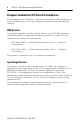
1769-L20, 1769-L30 CompactLogix™ Controllers European Communities (EC) Directive Compliance If this product has the CE mark it is approved for installation within the European Union and EEA regions. It has been designed and tested to meet the following directives.
1769-L20, 1769-L30 CompactLogix™ Controllers 5 Hazardous Location Considerations This equipment is suitable for use in Class I, Division 2, Groups A, B, C, D or non-hazardous locations only. The following WARNING statement applies to use in hazardous locations. WARNING ! EXPLOSION HAZARD · Substitution of components may impair suitability for Class I, Division 2. · Do not replace components or disconnect equipment unless power has been switched off or the area is known to be non-hazardous.
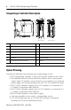
1769-L20, 1769-L30 CompactLogix™ Controllers CompactLogix Controller Description 1 2 13 3 12 4 5 6 7 7 8 8 15 11 10 9 9 1 14 2 3 1769-L20 controller 1769-L30 controller 1 DIN rail latch 8 Channel 0 RS-232 Port 2 panel mounting tab 9 Channel 0 default communication push button 3 tongue and groove slots 10 Channel 1 RS-232 Port 4 stationary bus connector 11 Channel 1 RS-232 Port Status LED 5 status LEDs 12 battery door 6 key switch 13 battery door label 7 Channel
1769-L20, 1769-L30 CompactLogix™ Controllers 7 Install the Controller The 1769-L20 and 1769-L30 controllers are suitable for use in an industrial environment when installed in accordance with these instructions. Specifically, this equipment is intended for use in clean, dry environments (Pollution Degree 2(1)) and with circuits not exceeding Over Voltage Category II(2) (IEC 60664-1).
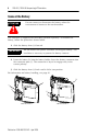
1769-L20, 1769-L30 CompactLogix™ Controllers Connect the Battery ATTENTION Do not connect or disconnect the battery unless the environment is known to be non-hazardous. ! The controller is shipped with the battery packed separately. To connect the battery, follow the procedure shown below. 1. Slide the battery door (a) forward. IMPORTANT Do not remove the plastic insulation covering the battery. The insulation is necessary to protect the battery contacts. 2.
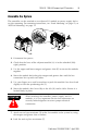
1769-L20, 1769-L30 CompactLogix™ Controllers 9 Assemble the System The controller can be attached to an adjacent I/O module or power supply before or after mounting. For mounting instructions, see “Panel Mounting” on page 10, or “DIN Rail Mounting” on page 11. C A D B F E B 1. Disconnect line power. 2. Check that the lever of the adjacent module (A) is in the unlocked (fully right) position. 3. Use the upper and lower tongue-and-groove slots (B) to secure the modules together. 4.
1769-L20, 1769-L30 CompactLogix™ Controllers Mount the System ATTENTION ! During panel or DIN rail mounting of all devices, be sure that all debris (metal chips, wire strands, etc.) is kept from falling into the controller. Debris that falls into the controller could cause damage while the controller is energized.
1769-L20, 1769-L30 CompactLogix™ Controllers 11 Panel Mounting Procedure Using Modules as a Template The following procedure allows you to use the assembled modules as a template for drilling holes in the panel. If you have sophisticated panel mounting equipment, you can use the dimensional template provided on page 10. Due to module mounting hole tolerance, it is important to follow these procedures: 1. On a clean work surface, assemble no more than three modules. 2.
1769-L20, 1769-L30 CompactLogix™ Controllers Grounding Considerations This product is intended to be mounted to a well-grounded mounting surface such as a metal panel. Additional grounding connections from the controller’s mounting tabs or DIN rail (if used), are not required unless the mounting surface cannot be grounded. Refer to Industrial Automation Wiring and Grounding Guidelines, Allen-Bradley publication 1770-4.1, for additional information.
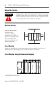
1769-L20, 1769-L30 CompactLogix™ Controllers 13 RS-232 Connections to the Controller The following illustrations show which cables can be used to connect to the controller. To connect two cables to the 1769-L30 controller, you must connect the straight cable end to Channel 0. 1769-L20 controller 1769-L30 controller NOTE: The Channel 0 port is locally grounded. Only Channel 1 of the 1769-L30 controller is electrically isolated.
1769-L20, 1769-L30 CompactLogix™ Controllers Default Communication Configuration Channel 0 and Channel 1 (1769-L30 controller only) have the following default communication configuration. Parameter Default Protocol DF1 full-duplex Baud Rate 19.
1769-L20, 1769-L30 CompactLogix™ Controllers 15 Using the Channel 0 Default Communication Push Button The Channel 0 Default Communication Push Button is located on the front of the controller in the lower right corner as shown in the illustration below. Use the Channel 0 Default Communication Push Button to change from the user-defined communication configuration to the default communications mode.
1769-L20, 1769-L30 CompactLogix™ Controllers Troubleshoot the Controller Using the LEDs Indicator Color/Status Description RUN Off No task(s) running Controller in Program mode Green One or more tasks are running Controller is in the Run mode Off No forces enabled Amber Forces enabled Amber Flashing One or more input or output addresses have been forced to an On or Off state, but the forces have not been enabled Off Battery supports memory Red Battery may not support memory, replace ba
69-L20, 1769-L30 CompactLogix™ Controllers 17 Flash Upgrade the Controller Firmware To update the firmware of a controller, first install a firmware upgrade kit. · An upgrade kit ships on a supplemental CD along with RSLogix 5000 software. · To download an upgrade kit, go to www.ab.com. Choose Product Support. Choose Firmware Updates. Update the Controller RSLogix 5000 software, revision 10.0 or later, lets you update controller firmware as part of the download sequence.
1769-L20, 1769-L30 CompactLogix™ Controllers Specifications Description 1769-L20 controller 1769-L30 controller Communication Ports (1) RS-232 (2) RS-232 User Memory 64K bytes 256K bytes Maximum number of I/O modules supported 8 I/O modules 16 I/O modules Maximum number of I/O banks supported 2 banks 3 banks Backplane Current 600 mA at +5V dc 0 mA at +24V dc 800 mA at +5V dc 0 mA at +24V dc Operating Temperature 0° to +60°C (+32° to +140°F) Storage Temperature -40° to +85°C (-40° t
1769-L20, 1769-L30 CompactLogix™ Controllers 19 Dimensions LOGIX5330 LOGIX5320 CompactLogix Controller RUN I/O FORCE OK BATT DCH0 CompactLogix RUN REM RUN I/O FORCE OK BATT DCH0 CompactLogix RUN PROG REM PROG A C B NOTE: All dimensions are in mm (in.). Hole spacing tolerance: ±0.4 mm (0.016 in.) A B 1769-L20 controller Height (A) 118 mm (4.649 in.) Width (B) 50 mm (1.97 in.) Depth (C) 87 mm (3.43 in.) 1769-L30 controller See page 10 for CompactLogix System dimensions.
1769-L20, 1769-L30 CompactLogix™ Controllers Battery Handling, Storing, and Transporting (Cat. No. 1747-BA; containing Sanyo CR14250SE battery cell) Handling ATTENTION ! Do not charge the batteries. An explosion could result or the cells could overheat causing burns. Do not open, puncture, crush, or otherwise mutilate the batteries. An explosion may result and/or toxic, corrosive, and flammable liquids would be exposed.
1769-L20, 1769-L30 CompactLogix™ Controllers ATTENTION ! 21 Do not incinerate or dispose of lithium batteries in general trash collection. Explosion or violent rupture is possible. Batteries should be collected for disposal in a manner to prevent against short circuiting, compacting, or destruction of case integrity and hermetic seal. For disposal, batteries must be packaged and shipped in accordance with transportation regulations, to a proper disposal site. The U.S.
1769-L20, 1769-L30 CompactLogix™ Controllers Notes: Publication 1769-IN047C-EN-P - April 2003
1769-L20, 1769-L30 CompactLogix™ Controllers 23 Notes: Publication 1769-IN047C-EN-P - April 2003
Notes: CompactLogix and RSLogix 5000 are trademarks of Rockwell Automation. Publication 1769-IN047C-EN-P - April 2003 Supersedes Publication 1769-IN047B-EN-P - June 2001 PN 957782-12 © 2003 Rockwell International Corporation. Printed in the U.S.A.