Quick Start CompactLogix 5370 L1 Controllers Catalog Numbers 1769-L16ER-BB1B, 1769-L18ER-BB1B, 1769-L18ERM-BB1B
Important User Information Solid-state equipment has operational characteristics differing from those of electromechanical equipment. Safety Guidelines for the Application, Installation and Maintenance of Solid State Controls (publication SGI-1.1 available from your local Rockwell Automation sales office or online at http://www.rockwellautomation.com/literature/) describes some important differences between solid-state equipment and hard-wired electromechanical devices.
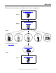
Where to Start Follow the path that matches your hardware and network configuration.
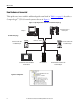
Where to Start How Hardware is Connected This quick start, in use with the additional quick starts listed in Table 1 on page 12, describes a CompactLogix™ 5370 L1 control system as shown in Figure 1.
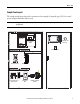
Where to Start Sample Panel Layout The sample panel layout shows the orientation of an example CompactLogix 5370 L1 control system using an EtherNet/IP network. IMPORTANT The graphic below is an example panel layout. The specific layout of CompactLogix 5370 L1 control systems varies by application.
Where to Start Notes: 6 Rockwell Automation Publication IASIMP-QS024B-EN-P - December 2012
Table of Contents Preface About the CompactLogix 5370 L1 Controllers . . . . . . . . . . . . . . . . . . . . . Choose to Integrate Optional Devices . . . . . . . . . . . . . . . . . . . . . . . . . . . . . Studio 5000 Environment . . . . . . . . . . . . . . . . . . . . . . . . . . . . . . . . . . . . . . . . Required Software . . . . . . . . . . . . . . . . . . . . . . . . . . . . . . . . . . . . . . . . . . . . . . . Parts List . . . . . . . . . . . . . . . . . . . . . . . . . . . . . . . . . . . . . . .
Table of Contents Chapter 4 Create a Logix Designer Project Before You Begin. . . . . . . . . . . . . . . . . . . . . . . . . . . . . . . . . . . . . . . . . . . . . . . . . What You Need. . . . . . . . . . . . . . . . . . . . . . . . . . . . . . . . . . . . . . . . . . . . . . . . . . Follow These Steps . . . . . . . . . . . . . . . . . . . . . . . . . . . . . . . . . . . . . . . . . . . . . . . Create a Project . . . . . . . . . . . . . . . . . . . . . . . . . . . . . . . . . . . . . . . . . . . . . . .
Preface This quick start describes how to use CompactLogix 5370 L1 controllers to install a simple CompactLogix 5370 L1 control system and execute a task with a local 1734 POINT I/O output module. The programming examples included are not complex, and offer solutions to verify that devices are functioning and communicating properly. IMPORTANT Consider the following points: • A typical CompactLogix 5370 L1 control system includes more components than listed in this quick start.
Preface • Configuring an EtherNet/IP network IMPORTANT You are not required to install nor configure an EtherNet/IP network to complete the tasks described in this quick start. However, before you can complete the tasks described in some of the publications listed on page 12, you must first install an EtherNet/IP network. For example, Chapter 4, on Create a Logix Designer Project on page 51 describes how to use ladder logic to test a 1734-OB4E output module.
Preface These features are available on CompactLogix 5370 L1 controllers: • Embedded 24V DC input nonisolated power supply • Secure Digital (SD) card for nonvolatile memory storage • Network connections: – USB (single port) – Support for EtherNet/IP network- Option to use the controller in device-level ring (DLR), linear, and star topologies on EtherNet/IP networks • I/O module options: – Sixteen embedded 24V DC digital input points – Sixteen embedded 24V DC digital output points – 1734 POINT I/O mo
Preface Choose to Integrate Optional Devices This table describes additional optional devices and their related documentation that you might use in a CompactLogix 5370 L1 control system on an EtherNet/IP network. You can view or download publications at http://www.rockwellautomation.com/literature/.
Preface Studio 5000 Environment The Studio 5000™ Engineering and Design Environment combines engineering and design elements into a common environment. The first element in the Studio 5000 environment is the Logix Designer application. The Logix Designer application is the rebranding of RSLogix™ 5000 software and will continue to be the product to program Logix5000 controllers for discrete, process, batch, motion, safety, and drive-based solutions.
Preface Required Software Before attempting to complete any of the tasks described in this publication, verify that your computer meets the following operating system and service pack compatibility requirements: • Microsoft Windows 7 Professional (64-bit) with Service Pack 1 • Microsoft Windows 7 Home Premium (64-bit) with Service Pack 1 • Microsoft Windows 7 Home Premium (32-bit) with Service Pack 1 • Microsoft Windows Server 2008 R2 Standard Edition with Service Pack 1 If your computer does not m
Preface Parts List Table 3 lists the hardware used in this quick start. Specific hardware requirements are listed at the beginning of each chapter. Table 3 - Parts Used with This Quick Start Quantity Cat. No. Description 1 or more N/A DIN rail (steel, not aluminum) 1 One of the following: CompactLogix 5370 L1 controller The tasks described in this publication use a 1769-L18ERM-BB1B controller.
Preface Table 4 - Additional Resources Resource Description Logix5000 Control Systems: Connect a Kinetix 350 Multi-axis Servo Drive System over an EtherNet/IP Network Quick Start, publication IASIMP-QS032 Describes basic steps required to include Kinetix 350 Multi-axis Servo drives over an EtherNet/IP network in a Logix5000 control system, including hardware, firmware, and software considerations.
Chapter 1 Prepare the CompactLogix 5370 L1 Controller Hardware This chapter describes how to install the hardware needed for your CompactLogix 5370 L1 control system. What You Need Table 5 lists the hardware components used in this chapter. Table 5 - Parts Used with This Quick Start Quantity Cat. No. Description 1 or more N/A DIN rail (steel, not aluminum) 1 One of the following: CompactLogix 5370 L1 controller The tasks described in this publication use a 1769-L18ERM-BB1B controller.
Chapter 1 Prepare the CompactLogix 5370 L1 Controller Hardware Follow These Steps Install the EtherNet/IP Network page 19 Install the Secure Digital Card page 20 Mount the Controller page 22 Install the Local Expansion Module Wire Power to the Controller page 23 DC 24-28V DC ok 50W max.
Prepare the CompactLogix 5370 L1 Controller Hardware Chapter 1 Install the EtherNet/IP Network You are not required to install an EtherNet/IP network to complete the tasks described in this quick start. You can complete the tasks via a USB connection to the CompactLogix 5370 L1 controller. However, we recommend that you install an EtherNet/IP network. You will likely complete some tasks described in the publications listed on page 12.
Chapter 1 Prepare the CompactLogix 5370 L1 Controller Hardware Install the Secure Digital Card The SD card provides nonvolatile storage for the CompactLogix 5370 L1 controller. You can store Logix Designer projects to an SD card or load a Logix Designer project from an SD card.
Prepare the CompactLogix 5370 L1 Controller Hardware Chapter 1 2. Open the door for the SD card. 3. Insert the SD card into the SD card slot. You can install the SD card in one orientation only. The beveled corner should be at the top. An orientation logo is printed on the card. If you feel resistance when inserting the SD card, pull it out and change the orientation. 4. Gently press the card until it clicks into place. 5. Close the SD card door.
Chapter 1 Prepare the CompactLogix 5370 L1 Controller Hardware Mount the Controller 1. Pull the locking tabs out. 2. Slide the controller into position on the DIN rail and push the locking tabs in. 3. Make sure the protective covering on the right side of the controller is removed. The protective covering must be removed to install a local expansion module, as described beginning on page 23.
Prepare the CompactLogix 5370 L1 Controller Hardware Chapter 1 Install the Local Expansion Module This quick start uses a 1734-OB4E POINT I/O output module in a local expansion module slot. 1. Make sure the DIN rail locking screw in the mounting base, for example, the 1734-TB mounting base, is in the vertical position. 2. Align the tongue and groove slots of the mounting base to the slots on the right side of the controller and push it back until it seats on the DIN rail. 3.
Chapter 1 Prepare the CompactLogix 5370 L1 Controller Hardware 6. Insert the module straight into the mounting base and press to secure. 7. Insert the RTB end opposite the handle into the base unit. The end has a curved section that engages with the mounting base. 8. Rotate the terminal block into the mounting base to lock it in place. 9. Snap the RTB handle into place on the module. 10. Connect an end cap to the right side of the module.
Prepare the CompactLogix 5370 L1 Controller Hardware Chapter 1 Wire Power to the Controller This quick start uses a 1606-XLP50E NEC Class 2/SELV switched-mode power supply to power the CompactLogix 5370 L1 controller. IMPORTANT This section describes how to wire power to the controller. Note that the controller is grounded by its connection to the DIN rail. 1. Verify that input power to the external power supply is turned off. 2. Mount the power supply on the DIN rail. 3.
Chapter 1 Prepare the CompactLogix 5370 L1 Controller Hardware 6. Open the top terminal on the removable connector. 7. Insert the wire connected to the 24V DC+ terminal on the external power supply to the VDC + terminal on the removable connector and close the terminal. 8. Connect a wire to a 24V DCterminal on the power supply. DC ok DC 24-28V 50W max. DC ok 9. Connect the other end of the wire to the VDC - terminal on the removable connector by repeating steps 6 and 7.
Prepare the CompactLogix 5370 L1 Controller Hardware Chapter 1 11. Secure the removable connector in place. This graphic shows the 1606-XLP50E switched-mode power supply connected to the CompactLogix 5370 L1 controller. DC 24-28V DC ok 50W max. DC ok 00:00:BC:2E:69:F6 2428V NEC Class 2 Power Supply 12. Turn on incoming power to the external power supply.
Chapter 1 Prepare the CompactLogix 5370 L1 Controller Hardware Make Network Connections You can make these connections to a CompactLogix 5370 L1 controller: • Make a USB Connection • Make EtherNet/IP Network Connections IMPORTANT This section describes both methods of connecting your computer to your CompactLogix 5370 L1 controller. This quick start was written under the assumption that you have installed an EtherNet/IP network.
Prepare the CompactLogix 5370 L1 Controller Hardware Chapter 1 Make EtherNet/IP Network Connections This section assumes you installed an EtherNet/IP network as described on page 19 and the network includes a 1783-EMS08T Stratix 6000 Ethernet managed switch. 1. Plug a 1585J-M4TBJM-1, Ethernet cable (straight-through) into a port on the Stratix 6000 switch. 8 7 6 5 00:00:BC:2E:69:F6 4 3 2 1 2. Plug the other end of the Ethernet cable into one of the Ethernet ports on the bottom of the controller.
Chapter 1 Prepare the CompactLogix 5370 L1 Controller Hardware Notes: 30 Rockwell Automation Publication IASIMP-QS024B-EN-P - December 2012
Chapter 2 Prepare the Computer and Load Controller Firmware In this chapter, you install and configure the necessary programming and configuration software on your computer and load firmware on your controller. Before You Begin Before you begin using this chapter, complete these tasks: • Verify that your computer meets the software’s system requirements for installation and use of the software listed in Table on page 14.
Chapter 2 Prepare the Computer and Load Controller Firmware What You Need Table 6 lists the components you use in this chapter. Table 6 - What You Need to Prepare the Computer Component Description Studio 5000 environment Environment that combines engineering and design elements into a common environment. Logix Designer application Software used to create a project the CompactLogix 5370 L3 controller uses in your application.
Prepare the Computer and Load Controller Firmware Chapter 2 Follow These Steps Install the Studio 5000 Environment page 34 Configure an EtherNet/IP Driver in RSLinx Classic Software page 36 Set the IP Address for the Computer page 38 Load the Controller Firmware page 41 Install Additional Software - Optional page 44 Rockwell Automation Publication IASIMP-QS024B-EN-P - December 2012 33
Chapter 2 Prepare the Computer and Load Controller Firmware Install the Studio 5000 Environment The Studio 5000 environment, version 21.00.00, installation process is configured so that, among other software applications, RSLinx Classic software, version 3.51.00, is automatically installed. The automatic installation option is enabled by default. You can change the installation setting and install RSLinx Classic software separately.
Prepare the Computer and Load Controller Firmware Chapter 2 3. Use the default selections and click Install. 4. Read the license agreement carefully. 5. Click Accept All. The installation process begins. When installation is complete, your computer will have the software necessary required to complete the tasks described in this publication. Among other software, your computer will have the following: • Studio 5000 Environment, version 21.00.00 • RSLinx Classic software, version 3.51.
Chapter 2 Prepare the Computer and Load Controller Firmware Automatic Installation of ControlFLASH Software ControlFLASH software is used to upgrade a CompactLogix 5370 L1 controller’s firmware revision. ControlFLASH software is automatically installed when you install the Studio 5000 environment. For more information on loading firmware on your controller, see Load the Controller Firmware on page 41. Configure an EtherNet/IP Driver in RSLinx Classic Software 1. Start the software. 2.
Prepare the Computer and Load Controller Firmware Chapter 2 3. From the Available Driver Types menu, choose EtherNet/IP Driver or Ethernet devices and click Add New. We recommend that you use EtherNet/IP Driver. The Add New RSLinx Driver dialog box appears. 4. Click OK to keep the default name. A Configure driver:AB_ETHxxx dialog box appears. The full name of the dialog box varies by what driver type was chosen in step 3. This example uses the EtherNet/IP Driver; the driver name is AB_ETHIP-1. 5.
Chapter 2 Prepare the Computer and Load Controller Firmware 6. Verify that the driver’s Status is Running and click Close. Set the IP Address for the Computer Your computer requires an Internet Protocol (IP) address to operate on an EtherNet/IP network. The IP address uniquely identifies the controller and is in the form xxx.xxx.xxx.xxx where each xxx is a number from 000…254 with some exceptions for reserved values. A computer’s IP address can be set automatically or manually.
Prepare the Computer and Load Controller Firmware Chapter 2 2. Click adapter settings. 3. Right-click Local Area Connection and choose Properties.
Chapter 2 Prepare the Computer and Load Controller Firmware 4. On the Networking tab, choose Internet Protocol Version 4 (TCP/IPv4) and click Properties. 5. Select Use the following IP address and enter an IP address and Subnet mask for your computer. 6. Record the IP address and subnet mask. 7. Click OK. 8. Close the Local Area Connection Properties dialog box.
Prepare the Computer and Load Controller Firmware Chapter 2 Load the Controller Firmware IMPORTANT This section assumes that you downloaded the controller firmware from the Rockwell Automation technical support website to install on your CompactLogix 5370 L1 controller. If not, download the firmware before following the steps in this section. The firmware is available with Logix Designer application or you can download it from the support website. Go to http://www.rockwellautomation.com/support/.
Chapter 2 Prepare the Computer and Load Controller Firmware 4. Click Next. 5. Select the controller catalog number and click Next.
Prepare the Computer and Load Controller Firmware Chapter 2 6. Expand the USB driver, and select your controller. 7. Click OK. 8. If it’s not in the position already, move the mode switch on the controller to the REM position. RUN REM PROG 9. Choose the desired firmware revision and click Next. TIP Consider the following: • If the Current Revision matches the firmware revision shown in the box below it, click Cancel. You are finished with this task. • This example uses firmware revision 21.001.23.
Chapter 2 Prepare the Computer and Load Controller Firmware 10. To start the firmware update, click Finish and then click Yes. Before the firmware upgrade begins, you see the following dialog box. Take the appropriate action for your application. In this example, the upgrade continues when OK is clicked. When the update completes, the status box informs you that the update was successful. Install Additional Software - Optional Depending on your application, you may need to install additional software.
Chapter 3 Configure the EtherNet/IP Network In this chapter, you assign an IP address to your CompactLogix 5370 L1 controller. This quick start does not describe how to use other devices on the EtherNet/IP network. It is common to use other devices on an EtherNet/IP network in a CompactLogix 5370 L1 control system. If you were to do so, for example, use a PanelView Plus terminal on an EtherNet/IP network, you need to assign an IP address to those devices.
Chapter 3 Configure the EtherNet/IP Network Configure the EtherNet/IP Network Before You Begin Before you begin using this chapter, complete these tasks: • The tasks described in Chapter 1, Prepare the CompactLogix 5370 L1 Controller Hardware on page 17, including the following: – Install the EtherNet/IP network. – Mount the controller and install the local expansion module. – Wire power to the controller. – Make network connection.
Configure the EtherNet/IP Network Chapter 3 What You Need Table 7 lists the software components you use in this chapter. Table 7 - What You Need to Configure the EtherNet/IP Network Component Description Studio 5000 environment Environment that combines engineering and design elements into a common environment. Logix Designer application Software used to create a project the CompactLogix 5370 L1 controller use in your application.
Chapter 3 Configure the EtherNet/IP Network Configure the EtherNet/IP Network Assign an IP Address to the Controller over a USB Connection At initial powerup, the CompactLogix 5370 L1 controller does not have an IP address. Use RSLinx Classic software over a USB connection to assign an IP address. The following steps will work only if the computer with RSLinx Classic software is connected to the controller via a USB connection.
Configure the EtherNet/IP Network Chapter 3 5. Click the Port Configuration tab. 6. For Network Configuration Type, click Static to permanently assign this configuration to the port. IMPORTANT The controller’s default configuration is Dynamic. When the controller is configured for Dynamic, on a power cycle, it clears the current IP address and resumes sending BOOTP requests. 7. Enter the IP address and Network Mask for the controller. 8. Enter other network parameters, if necessary. 9. Click OK.
Chapter 3 Configure the EtherNet/IP Network Configure the EtherNet/IP Network Notes: 50 Rockwell Automation Publication IASIMP-QS024B-EN-P - December 2012
Chapter 4 Create a Logix Designer Project In this chapter you create a Logix Designer project. In the project you use ladder logic to create a push button that controls a light on a digital output module. You learn how to complete the following tasks: • Create a Logix Designer project. • Configure your 1769-L18ERM-BB1B controller. • Add a local expansion module to the project. • Add ladder logic to the project to test the local expansion module. • Download the project to the controller.
Chapter 4 Create a Logix Designer Project Before You Begin Before you begin, complete these tasks: • The tasks described in Chapter 1, Prepare the CompactLogix 5370 L1 Controller Hardware on page 17, including the following: – – – – • Install the EtherNet/IP network. Install the controller and the local expansion module. Wire power to the controller. Make network connections.
Create a Logix Designer Project Chapter 4 Follow These Steps Create a Project page 54 Configure the Controller page 55 Add a Local Expansion Module page 58 Add Ladder Logic to Test the Local Expansion Module page 60 Download to the Controller page 63 Rockwell Automation Publication IASIMP-QS024B-EN-P - December 2012 53
Chapter 4 Create a Logix Designer Project Create a Project 1. Start the application. 2. Click New Project. The New Controller dialog box appears. 3. Choose your controller and name the project. 4. Click Next.
Create a Logix Designer Project Chapter 4 5. Set Expansion I/O to a number that exactly matches the number of 1734 POINT I/O modules physically installed in the system. In this case, the value is 1 Module. 6. Click Finish. Configure the Controller 1. Verify that the mode switch on the controller is in the REM position. RUN REM PROG 2. Click the RSWho icon.
Chapter 4 Create a Logix Designer Project 3. In the Who Active dialog box, expand the path to the controller and select it. 4. Click Set Project Path. By clicking this button, you set the path and do not have to browse to the controller each time you use an option in the Who Active dialog. 5. Click Go Online. You must be online to set the controller’s IP address in the Logix Designer project. 6. Click Download twice on successive dialog boxes. 7. Click Yes to change the controller mode to Remote Run. 8.
Create a Logix Designer Project Chapter 4 10. Use the tabs on the Controller Properties dialog box to configure the controller. The IP address is set on the Internet Protocol tab. IMPORTANT Make sure you set an IP Address and Subnet Mask that matches the values set in Set the IP Address for the Computer on page 38. There are many configurable parameters on various tabs in the Controller Properties dialog box.
Chapter 4 Create a Logix Designer Project Add a Local Expansion Module 1. Right-click PointIO and choose New Module. The Select Module Type dialog box appears. 2. Select the 1734-OB4E module and click Create. TIP You can use the Search feature in Logix Designer application to quickly find the I/O module you need to add to your project. The New Module dialog box appears for the module created.
Create a Logix Designer Project Chapter 4 3. Use the tabs to create the parameters for the I/O module. IMPORTANT For the purposes of this exercise, make sure you change the Module Definition parameters so Electronic Keying is set to Disable Keying. 4. When the module configuration is complete, click OK. The module is added to the I/O Configuration.
Chapter 4 Create a Logix Designer Project Add Ladder Logic to Test the Local Expansion Module IMPORTANT If you do not have a 1734-OB4E module, you can use ladder logic with an embedded output point on the CompactLogix 5370 L1 controller in a similar fashion. When using an embedded output point, instead of choosing an output point on the local expansion module, as described in step 13 on page 62, you choose an embedded digital output point on the CompactLogix 5370 L1 controller. 1.
Create a Logix Designer Project Chapter 4 4. Double-click the ? in the Examine On element. 5. Type PB (for push button). 6. Press Enter. 7. Right-click PB and choose New ‘PB’. 8. Keep the default settings and click one of the Create options.
Chapter 4 Create a Logix Designer Project 9. Double-click the ? in the Output Energize element. 10. Name the Output Energize element OB4E_Light and press Enter. IMPORTANT Do not use spaces in the tag name. Use underscores (_) instead. 11. Right-click the OB4E_Light tag name and choose New ‘OB4E_Light’. OB4E_Light is an alias tag for the I/O point tag name. With an alias tag, you can assign a simple name to a physical I/O point address. 12. From the Type pull-down menu, choose Alias. 13.
Create a Logix Designer Project Chapter 4 14. Close the dialog box. The graphic shows the Output Energize after assigning the Alias tag to a point on the output module. 15. Save your changes. Download to the Controller 1. From the mode pull-down menu, choose Download. 2. When the dialog box appears with information about the download, click Download. 3. Click Yes to change the controller mode to Remote Run mode.
Chapter 4 Create a Logix Designer Project 4. Move the mode switch on your controller to the RUN position. RUN REM PROG 5. In the Main Routine, select the PB Examine On instruction. 6. Press Ctrl+T to toggle the state from 0 to 1, or Off to On. 7. Verify that the status indicator on the digital output module turns on after you toggle the state to 1 or On. 8. Press Ctrl+T to toggle the state back to 0 or Off. 9. Go Offline.
Appendix A Understanding Other Application Options This chapter describes two application options available with a CompactLogix 5370 L1 controller: • Using the controller in a DLR network topology • Using the controller in an application that includes Integrated Motion on an EtherNet/IP network - 1769-L18ERM-BB1B controller only IMPORTANT This chapter does not describe specific steps required to use the CompactLogix 5370 L1 controller in applications with DLR networks or Integrated Motion over an Et
Appendix A Understanding Other Application Options DLR Network Topology A DLR network topology is a single-fault-tolerant ring network in which DLR-capable Rockwell Automation devices use embedded technology and dual EtherNet/IP ports to establish a network that is resilient to single points of failure, recovers faster when single faults occur, and does not require switches.
Understanding Other Application Options Appendix A Follow These Steps Begin Physical Device Installation 002 1734-AENTR POINT I O Module Status Network Activity Network Status Link 1 Activity/ Status Point Bus Status System Power IP ADDRESS Field Power Link 2 Activity/ Status Create a Logix Designer Project Complete Physical Device Installation 002 1734-AENTR POINT I O Module Status Network Activity Network Status Link 1 Activity/ Status Point Bus Status System Power IP ADDRESS Field Power
Appendix A Understanding Other Application Options Integrated Motion on the EtherNet/IP Network Integrated Motion on the EtherNet/IP network is an integrated motion solution on a standard, unmodified EtherNet/IP network that delivers high performance with lower costs and simpler design or configuration when compared to traditional, multi-network motion applications. The 1769-L18ERM-BB1B controller supports Integrated Motion on the EtherNet/IP network.
Index C CompactLogix 5370 L1 controllers available 10 devices to integrate 12 features 11 ControlFLASH software 14, 32 install 36 controller firmware load 41 D devices Kinetix 350 drives 12 PanelView Plus terminals 12 POINT I/O modules 12 PowerFlex 40 drives 12 PowerFlex 70 drives 12 to integrate in controller application 12 DLR network topology 65, 66 E EtherNet/IP network configure 45 connection 29 network topologies 11, 66 F features common to all controllers 11 firmware load on controller 41 H hardw
Index Notes: 70 Rockwell Automation Publication IASIMP-QS024B-EN-P - December 2012
Rockwell Automation Support Rockwell Automation provides technical information on the Web to assist you in using its products. At http://www.rockwellautomation.com/support, you can find technical manuals, technical and application notes, sample code and links to software service packs, and a MySupport feature that you can customize to make the best use of these tools. You can also visit our Knowledgebase at http://www.rockwellautomation.