Installation Instructions Compact I/O Thermocouple/mV Input Module Catalog Number 1769-IT6 Topic Page Important User Information 2 Hazardous Location Considerations 3 Preventing Electrostatic Discharge 4 Removing Power 4 About the Thermocouple/mV Input Module 5 About the Compact I/O System 5 Install the Thermocouple/mV Input Module 7 Mount Expansion I/O 8 Mount the Module to a Panel 9 Mount the Module to a DIN Rail 10 Replace a Single Module within a System 10 Wire the Thermocouple
Compact I/O Thermocouple/mV Input Module Important User Information Solid state equipment has operational characteristics differing from those of electromechanical equipment. Safety Guidelines for the Application, Installation and Maintenance of Solid State Controls (publication SGI-1.1 available from your local Rockwell Automation sales office or online at http://www.rockwellautomation.
Compact I/O Thermocouple/mV Input Module 3 Hazardous Location Considerations This equipment is suitable for use in Class I, Division 2, Groups A, B, C, D or nonhazardous locations only. This Warning statement applies to use in hazardous locations. WARNING Explosion Hazard • Substitution of components may impair suitability for Class I, Division 2. • Do not replace components or disconnect equipment unless power has been switched off or the area is known to be nonhazardous.
Compact I/O Thermocouple/mV Input Module Preventing Electrostatic Discharge ATTENTION Electrostatic discharge can damage integrated circuits or semiconductors if you touch bus connector pins or the terminal block. Follow these guidelines when you handle the module: • • • • • • Touch a grounded object to discharge static potential. Wear an approved wrist-strap grounding device. Do not touch the bus connector or connector pins. Do not touch circuit components inside the module.
Compact I/O Thermocouple/mV Input Module 5 About the Thermocouple/mV Input Module The thermocouple/mV module receives and stores digitally-converted thermocouple and/or millivolt analog data from any combination of as many as six thermocouple or millivolt analog sensors. Each input channel is individually configurable via software for a specific input device and provides open-circuit, over-range, and under-range detection and indication.
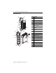
Compact I/O Thermocouple/mV Input Module Module Description 1 2a Item Description 1 Bus lever (with locking function) 2a Upper-panel mounting tab 2b Lower-panel mounting tab 3 Module status indicator 4 Module door with terminal identification label 5a Movable bus connector with female pins 5b Stationary bus connector with male pins 6 Nameplate label 7a Upper tongue-and-groove slots 7b Lower tongue-and-groove slots 8a Upper DIN-rail latch 8b Lower DIN-rail latch 9 Write-on labe
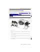
Compact I/O Thermocouple/mV Input Module 7 Install the Thermocouple/mV Input Module The module can be attached to the controller or an adjacent I/O module before or after mounting. For mounting instructions, see Mount the Module to a Panel on page 9, or Mount the Module to a DIN Rail on page 10. To work with a system that is already mounted, see Replace a Single Module within a System on page 10.
Compact I/O Thermocouple/mV Input Module 6. To allow communication between the controller and module, move the bus lever fully to the left (4) until it clicks, making sure it is locked firmly in place. ATTENTION When attaching I/O modules, it is very important that the bus connectors are securely locked together to be sure of proper electrical connection. 7. Attach an end-cap terminator (5) to the last module in the system by using the tongue-and-groove slots as before. 8.
Compact I/O Thermocouple/mV Input Module 9 Mount the Module to a Panel Mount the module to a panel by using two screws per module. Use M4 or #8 panhead screws. Mounting screws are required on every module. Mount the Module to a Panel by Using the Dimensional Template For more than 2 modules: (number of modules-1) x 35 mm (1.38 in.). End Cap Compact I/O 122.6 ±0.2 (4.826 ±0.008) Compact I/O All dimensions are in mm (in.). Hole spacing tolerance: ±0.4 mm (0.016 in.). 28.5 (1.12) 35 (1.
Compact I/O Thermocouple/mV Input Module Mount the Module to a DIN Rail The module can be mounted by using these DIN rails: 35 x 7.5 mm (EN 50 022 - 35 x 7.5) or 35 x 15 mm (EN 50 022 - 35 x 15). Before mounting the module on a DIN rail, close the DIN rail latches. Press the DIN rail mounting area of the module against the DIN rail. The latches will momentarily open and lock into place.
Compact I/O Thermocouple/mV Input Module 11 6. Before installing the replacement module, be sure that the bus levers on the module to be installed and on the right-side adjacent module are in the unlocked (fully right) position. 7. Slide the replacement module into the open slot. 8. Connect the modules by locking (fully left) the bus levers on the replacement module and the right-side adjacent module. 9. Replace the mounting screws (or snap the module onto the DIN rail).
Compact I/O Thermocouple/mV Input Module • Ground the shield drain wire at only one end. The typical location is the same point as the sensor ground reference. – For grounded thermocouples or millivolt sensors, this is at the sensor end. – For insulated/ungrounded thermocouples, this is at the module end. Contact your sensor manufacturer for additional details. • If it is necessary to connect the shield drain at the module end, connect it to earth ground by using a panel or DIN-rail mounting screw.
Compact I/O Thermocouple/mV Input Module 13 Wire the Finger-safe Terminal Block When wiring the terminal block, keep the finger-safe cover in place. 1. Loosen the terminal screws to be wired. 2. Route the wire under the terminal pressure plate. You can use the bare wire or a spade lug. The terminals accept a 6.35 mm (0.25 in.) spade lug. TIP The terminal screws are non-captive. Therefore, it is possible to use a ring lug (1/4 in. maximum o.d. with a 0.139 in. minimum i.d. (M3.5)) with the module. 3.
Compact I/O Thermocouple/mV Input Module Wire Input Devices to the 1769-IT6 Module ATTENTION Be careful when stripping wires. Wire fragments that fall into a module could cause damage at powerup. Once wiring is complete, be sure that the module is free of all metal fragments.
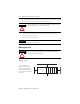
Compact I/O Thermocouple/mV Input Module 15 Terminal Block with CJC Sensors and Thermocouple Junctions CJC Sensor CJC 0+ NC + IN 0+ + - Ungrounded Thermocouple CJC 0IN 3+ IN 1 + IN 3- IN 1- Within 10V DC + IN 4+ IN 4IN 5+ Grounded Thermocouple IN 0- IN 2+ IN 2- - CJC 1- Grounded Thermocouple IN 5NC CJC 1+ CJC Sensor TIP When using an ungrounded thermocouple, the shield must be connected to ground at the module end.
Compact I/O Thermocouple/mV Input Module Cold-junction Compensation (CJC) You must compensate for the cold-junction temperature—the temperature at the module’s terminal junction between the thermocouple wire and the input channel—to obtain accurate readings from each of the channels. Two cold-junction compensating thermistors have been integrated in the terminal block, as shown on page 15. ATTENTION Do not remove or loosen the cold-junction compensating thermistor assemblies on the terminal block.
Compact I/O Thermocouple/mV Input Module 17 I/O Memory Mapping The input data file contains the analog values of the inputs.
Compact I/O Thermocouple/mV Input Module Configuration Data File During initial system configuration, you normally manipulate the bits from the configuration data file with programming software, such as RSLogix 500 or RSNetWorx for DeviceNet software. Graphical screens simplify configuration. However, some products, like the 1769-ADN DeviceNet adapter, also let you alter the bits as part of the control program, by using communication rungs. In this case, you need to understand the bit arrangement.
Compact I/O Thermocouple/mV Input Module 19 Configuration Data File Enable Channel Data Format Input Type Temp.
Compact I/O Thermocouple/mV Input Module Module Configuration Word Word 6 of the configuration data file contains the Enable/Disable Cyclic Calibration bit. To select Make these bit settings 15 14 13 12 11 10 9 8 7 6 5 4 3 2 1 Enable/Disable Enabled(1) Cyclic Disabled Calibration (1) 0 0 1 When enabled, an autocalibration cycle is performed on all enabled channels every 5 min.
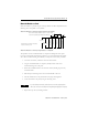
Compact I/O Thermocouple/mV Input Module 21 Technical Specifications - 1769-IT6 Attribute 1769-IT6 Module error over full temperature range (0…60 °C (32…140 °F)) See Calibrated Accuracy - 1769-IT6 on page 22. CJC sensor accuracy ±0.3 °C (±0.54 °F) CJC accuracy ±1.0 °C (±1.8 °F) Power supply distance rating 8 (The module cannot be more than 8 modules away from the Compact I/O power supply. See page 7 for suggested placement when using AC power supplies.
Compact I/O Thermocouple/mV Input Module Environmental Specifications - 1769-IT6 Attribute 1769-IT6 Vibration, operating 10…500 Hz, 5 g, 0.030 in. peak-to-peak Relay operation 2 g(1) Shock, operating 30 g, 11 ms panel-mounted (20 g, 11 ms DIN rail-mounted) Relay operation 7.
Compact I/O Thermocouple/mV Input Module 23 Calibrated Accuracy - 1769-IT6 Input Type(1) Accuracy for 10 Hz, 50 Hz, and 60 Hz Filters(2) (max) @ 25 °C (77 °F) @ 0…60 °C (32…140 °F) Thermocouple K (-230…1370 °C (-382…2498 °F)) ±1 °C (±1.8 °F) ±1.5 °C (±2.7 °F) Thermocouple K (-270…-230 °C (-454…-382 °F)) ±7.5 °C (±13.5 °F) ±10 °C (±18 °F) Thermocouple E (-210…1000 °C (-346…1832 °F)) ±0.5 °C (±0.9 °F) ±0.8 °C (±1.4 °F) Thermocouple E (-270…-210 °C (-454…-346 °F)) ±4.2 °C (±7.6 °F) ±6.
Additional Resources These documents contain additional information concerning related Rockwell Automation products. Resource Description MicroLogix 1500 Programmable Controllers User Manual, publication 1764-UM001 Provides a more detailed description of how to install and use your Compact I/O module with the MicroLogix 1500 programmable controller.