
User Manual


Rockwell Automation Publication 1769-UM004B-EN-P - March 2010 69
Module Data, Status, and Channel Configuration Chapter 4
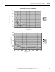
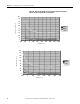
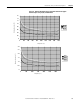
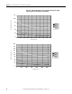
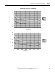
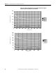
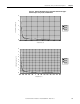
Table 6 - Effective Resolution versus Input Filter Selection for Millivolt Inputs
The table below identifies the number of significant bits used to represent the
input data for each available filter frequency. The number of significant bits is
defined as the number of bits that will have little of no jitter due to noise, and is
used in defining the effective resolution.
Determining Module
Update Time
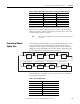
The module update time is defined as the time required for the module to sample
and convert the input signals of all enabled input channels and provide the
resulting data values to the processor. Module update time can be calculated by
adding the sum of all enabled channel’s times. The module sequentially samples
the enabled channels in a continuous loop as shown below.
Channel update time is dependent upon the input filter selection. This table
shows the channel update times.
Filter Frequency ±50 mV ±100 mV
10 Hz 6 µV 6 µV
50 Hz 9 µV 12 µV
60 Hz 9 µV 12 µV
250 Hz 125 µV 150 µV
500 Hz 250 µV 300 µV
1 kHz 1000 µV 1300 µV
TIP
The resolutions provided by the filters apply to the raw/proportional data
format only.
Channel 4 Disabled Channel 5 Disabled No Thermocouple Calibration Not Active
Sample
Channel 0
Sample
Channel 1
Sample
Channel 2
Sample
Channel 3
Enabled Enabled Enabled Enabled
Sample
Channel 4
Sample
Channel 5
Enabled Enabled TC Enabled
Sample
CJC
Calibration
Active
Perform
Calibration
Table 7 - Channel Update Time
Filter Frequency Channel Update Time
10 Hz 303 ms
50 Hz 63 ms
60 Hz 53 ms
250 Hz 15 ms
500 Hz 9 ms
1 kHz 7 ms