
User Manual


38 Rockwell Automation Publication 1769-UM004B-EN-P - March 2010
Chapter 4 Module Data, Status, and Channel Configuration
Accessing Input Image
File Data
The input image file represents data words and status words. Input words 0…5
hold the input data that represents the value of the analog inputs for channels
0…5. These data words are valid only when the channel is enabled and there are
no errors. Input words 6 and 7 hold the status bits. To receive valid status
information, the channel must be enabled.
You can access the information in the input image file by using the programming
software configuration screen. For information on configuring the module in a:
• MicroLogix 1500 system by using RSLogix 500 software,
see Appendix
E.
• CompactLogix system by using RSLogix 5000 software,
see Appendix
F.
• 1769-ADN DeviceNet adapter by using RSNetWorx software,
see Appendix
G.
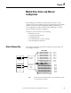
Input Data File
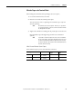
The input data table allows you to access module read data for use in the control
program, via word and bit access. The data table structure is shown in this table.
Input Data Values
Data words 0…5 correspond to channels 0…5 and contain the converted analog
input data from the input device. The most significant bit, bit 15, is the sign bit
(SGN).
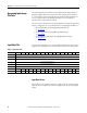
Table 1 - Input Data Table
Word/Bit
(1)
1514131211109876543210
0 Analog Input Data Channel 0
1 Analog Input Data Channel 1
2 Analog Input Data Channel 2
3 Analog Input Data Channel 3
4 Analog Input Data Channel 4
5 Analog Input Data Channel 5
6 OC7OC6OC5OC4OC3OC2OC1OC0S7S6S5S4S3S2S1S0
7 U0 O0U1O1U2O2U3O3U4O4U5O5U6O6U7O7
(1) Changing bit values is not supported by all controllers. Refer to your controller manual for details.