
User Manual


Rockwell Automation Publication 1769-UM004B-EN-P - March 2010 19
Quick Start for Experienced Users Chapter 2
Be sure the bus lever is locked firmly in place.
6. Attach an end cap terminator (5) to the last module in the system by using
the tongue-and-groove slots as before.
7. Lock the end cap bus terminator (6).
Follow these guidelines when wiring the module:
General Guidelines
• Power and input wiring must be in accordance with Class I, Division 2
wiring methods, Article 501-4(b) of the National Electric Code, NFPA 70,
and in accordance with the authority having jurisdiction.
• Channels are isolated from one another by ±10V DC maximum.
• Route field wiring away from any other wiring and keep it as far as possible
from sources of electrical noise, such as motors, transformers, contactors,
and AC devices. As a general rule, allow at least 15.2 cm (6 in.) of
separation for every 120V of power.
• Routing field wiring in a grounded conduit can reduce electrical noise.
• If field wiring must cross AC or power cables, be sure that they cross at
right angles.
• If multiple power supplies are used with analog millivolt inputs, the power
supply commons must be connected.
Terminal Block Guidelines
• Do not use the module’s NC terminals as connection points.
• Do not tamper with or remove the CJC sensors on the terminal block.
Removal of either one or both sensors will reduce accuracy.
• For millivolt sensors, use Belden 8761 shielded, twisted-pair wire (or
equivalent) to be sure of proper operation and high immunity to electrical
noise.
• For a thermocouple, use the shielded, twisted-pair thermocouple extension
lead wires specified by the thermocouple manufacturer. Using the incorrect
type of thermocouple extension wire or not following the correct polarity
will cause invalid readings.
ATTENTION: When attaching I/O modules, it is very important
that the bus connectors are securely locked together to be sure of
proper electrical connection.
IMPORTANT
A 1769-ECR or 1769-ECL right or left end cap respectively must be
used to terminate the end of the 1769 communication bus.
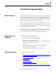
Step 3 Wire the module. Reference
Chapter
3
(Installation and Wiring)