
User Manual


18 Rockwell Automation Publication 1769-UM004B-EN-P - March 2010
Chapter 2 Quick Start for Experienced Users
The module’s maximum current draw is:
• 100 mA for 5V DC.
• 40 mA for 24V DC.
1. Check that the bus lever of the module to be installed is in the unlocked
(fully right) position.
2. Use the upper and lower tongue-and-groove slots (1) to secure the
modules together (or to a controller).
3. Move the module back along the tongue-and-groove slots until the bus
connectors (2) line up with each other.
4. Push the bus lever back slightly to clear the positioning tab (3) by using
your fingers or a small screwdriver.
5. Move the bus lever fully to the left (4) until it clicks to allow
communication between the controller and module.
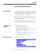
Step 1
Be sure that your 1769 system power supply
(1)
has sufficient current
output to support your system configuration.
Reference
Chapter
3
(Installation and Wiring)
(1) The system power supply could be catalog number 1769-PA2, 1769-PB2, 1769-PA4, 1769-PB4, or the internal supply of the
MicroLogix 1500 packaged controller.
Step 2 Attach and lock the module. Reference
Chapter
3
(Installation and Wiring)
TIP
The module can be panel or DIN rail mounted. Modules can be
assembled before or after mounting.
ATTENTION: Remove power before removing or inserting this module. If
you remove or insert a module with power applied, an electrical arc may
occur.
IMPORTANT
To reduce the effects of electrical noise, install the 1769-IT6 module at
least two slots away from Compact I/O 120/240V AC power supplies.
6
5
4
3
1
1
2