
User Manual


140 Rockwell Automation Publication 1769-UM004B-EN-P - March 2010
Appendix E Module Configuration by Using a MicroLogix 1500 System and RSLogix 500 Software
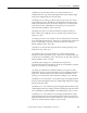
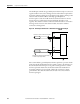
For example, to obtain the general status of channel 2 of the module located in
slot e, use address I:e.6/2.
Figure 56 - General Status of Channel 2
1769-IT6 Configuration File
The configuration file contains information you use to define the way a specific
channel functions. The configuration file is explained in more detail in
Configuring Channels
on page 40.
The configuration file is modified by using the programming software
configuration screen. For an example of module configuration by using RSLogix
500 software, see Configuring the 1769-IT6 Module in a MicroLogix 1500
System on page 141.
TIP
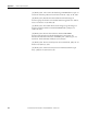
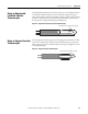
The end cap does not use a slot address.
Table 16 - Software Configuration Ch
annel Defaults
(1)
(1)
May be overridden by the software.
Parameter Default Setting
Disable/Enable Channel Disable
Filter Frequency 60 Hz
Input Type Thermocouple Type J
Data Format Raw/Proportional
Temperature Units °C
Open-circuit Response Upscale
Disable Cyclic Calibration Enable
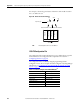
I:e.6/2
Input File Type
Slot
Word
Bit
Bit Delimiter
Word Delimiter
Element Delimiter
0123
Adapter
Compact I/O
Compact I/O
Compact I/O
End Cap
Slot Number