
User Manual


Rockwell Automation Publication 1769-UM004B-EN-P - March 2010 13
Overview Chapter 1
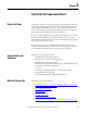
Figure 1 - Hardware Features
Item Description
1 Bus lever
2a Upper-panel mounting tab
2b Lower-panel mounting tab
3 Module status indicator
4 Module door with terminal identification label
5a Movable bus connector (bus interface) with female pins
5b Stationary bus connector (bus interface) with male pins
6 Nameplate label
7a Upper tongue-and-groove slots
7b Lower tongue-and-groove slots
8a Upper DIN-rail latch
8b Lower DIN-rail latch
9 Write-on label for user identification tags
10 Removable terminal block (RTB) with finger-safe cover
10a RTB upper-retaining screw
10b RTB lower-retaining screw
11 CJC sensors
10a
10b
4
10
11
11
2b
3
2a
1
5a
9
5b
6
7a
7b
8b
7b
8a
7a
1769-IT6
DANGER
Do Not Remove RTB Under Power
Unless Area is Non-Hazardous
Ensure
Adjacent Bus Lever is
Unlatched/Latched Before/After
Removing/Inserting Module
CJC 0-
IN 5+
NC
CJC 1+
IN 3+
IN 4+
IN 4-
IN 5-
CJC 0+
NC
IN 0-
IN 1-
IN 2-
IN 0+
IN 1+
IN 2+
CJC 1-
IN 3-
OK
Thermocouple/mV
OK
Thermocouple/mV