
Owner's manual


Rockwell Automation Publication 1769-UM005B-EN-P - March 2012 91
Appendix
A
Module Addressing and Programming with
MicroLogix 1500 and RSLogix 500
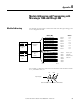
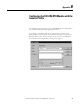
Module Addressing
The module uses eight input words for data and status bits (input image), and
seven configuration words.
For example, to obtain the general status of channel 2 of the module located in
slot e, use address I:e.6/2.
Channel 0 Data Word
Word 0
Word 1
Word 2
Word 3
Word 4
Word 5
Channel 1 Data Word
Channel 2 Data Word
Channel 3 Data Word
General/Open-Circuit Status Bits
Over-/Under-range Bits
Channel 0 Configuration Word
Channel 1 Configuration Word
Channel 2 Configuration Word
Channel 3 Configuration Word
I:e.0
I:e.1
I:e.2
I:e.3
I:e.4
I:e.5
Word 0
Word 1
Word 2
Word 3
Address
Input Image
8 words
Configuration
File
7 words
slot e
slot e
Input Image
File
Configuration
File
Memory Map
Bit 15 Bit 0
Refer to your
controller
manual for the
addresses.
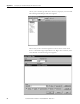
Channel 3 Data Word
Channel 3 Data Word
Word6
Word 7
I:e.6
I:e.7
Channel 4 Configuration Word
Channel 5 Configuration Word
Word 4
Word 5
Module Configuration Word Word 6
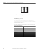
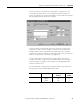
I:e.6/2
Input File Type
Slot
Word
Bit
Bit Delimiter
Word Delimiter
Element Delimiter