
Owner's manual


Rockwell Automation Publication 1769-UM005B-EN-P - March 2012 47
Module Data, Status, and Channel Configuration Chapter 4
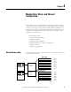
Input Data File
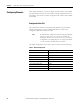
The input data table lets you access RTD input module read data for use in the
control program, via word and bit access. The data table structure is shown in
table below.
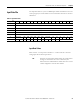
Input Data Values
Data words 0…5 correspond to channels 0…5 and contain the converted
analog input data from the input device.
Table 4 - Input Data Table
Word/Bit
(1)
1514131211109876543210
0 Analog Input Data Channel 0
1 Analog Input Data Channel 1
2 Analog Input Data Channel 2
3 Analog Input Data Channel 3
4 Analog Input Data Channel 4
5 Analog Input Data Channel 5
6 Not Used OC5 OC4 OC3 OC2 OC1 OC0 Not Used S5 S4 S3 S2 S1 S0
7 U0 O0U1O1U2O2U3O3U4O4U5O5 Not Used
(1) Modifying bit values is not supported by all controllers. Refer to your controller manual for details.
TIP
Status bits for a particular channel reflect the configuration
settings for that channel. To receive valid status, the
channel must be enabled and the module must have stored
a valid configuration word for that channel.