
Owner's manual


Rockwell Automation Publication 1769-UM005B-EN-P - March 2012 45
Chapter
4
Module Data, Status, and Channel
Configuration
After installation of the 1769-IR6 RTD/resistance input module, you must
configure it for operation, usually using the programming software compatible
with the controller (for example, RSLogix 500™ or RSLogix 5000™). Once
configuration is complete and reflected in ladder logic, you will need to get the
module up and running and then verify its operation. This chapter includes
information on the following:
· module memory map
· accessing input image file data
· configuring channels
· configuring periodic calibration
· preparing ladder logic to reflect the configuration
· running the module
· verifying the configuration
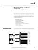
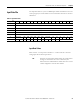
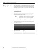
Module Memory Map
The module uses eight input words for data and status bits (input image), and
seven configuration words.
Channel 0 Data Word
Word 0
Word 1
Word 2
Word 3
Word 4
Word 5
Channel 1 Data Word
Channel 2 Data Word
Channel 3 Data Word
General/Open-Circuit Status Bits
Over-/Under-range Bits
Channel 0 Configuration Word
Channel 1 Configuration Word
Channel 2 Configuration Word
Channel 3 Configuration Word
Word 0
Word 1
Word 2
Word 3
Input Image
8 words
Configuration
File
7 words
slot e
slot e
Input Image
File
Configuration
File
Memory Map
Bit 15 Bit 0
Channel 4 Data Word
Channel 5 Data Word
Word 6
Word 7
Channel 4 Configuration Word
Channel 5 Configuration Word
Word 4
Word 5
Module Configuration Word Word 6