
Owner's manual


16 Rockwell Automation Publication 1769-UM005B-EN-P - March 2012
Chapter 1 Overview
Hardware Features
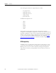
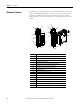
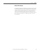
The RTD/resistance module contains a removable terminal block (spare part
number 1769-RTBN18) providing connections for six 3-wire inputs for any
combination of RTD and resistance input devices. Channels are wired as
differential inputs. The illustration below shows the hardware features of the
module.
10a
10b
4
10
2b
3
2a
1
5a
9
5b
6
7a
7b
8b
7b
8a
7a
1769-IR6
DANGER
Do Not Remove RTB Under Power
Unless Area is Non-Hazardous
Ensure Adjacent
Bus Lever is Unlatched/Latched
Before/After
Removing/Inserting Module
S
E
NS
E
3
E
X
C
5
R
T
N
5
R
T
N
2
R
T
N
3
-
S
E
N
S
E
4
R
T
N
4
S
E
N
S
E
5
E
X
C
3
E
X
C
0
R
TN
0
S
E
N
S
E
1
E
X
C
2
S
E
N
S
E
0
E
X
C
1
R
TN
1
S
E
N
S
E
2
E
X
C
4
OK
Analog
OK
Analog
Item Description
1 bus lever (with locking function)
2a upper panel mounting tab
2b lower panel mounting tab
3 module status indicator
4 module door with terminal identification label
5a movable bus connector with female pins
5b stationary bus connector with male pins
6 nameplate label
7a upper tongue-and-groove slots
7b lower tongue-and-groove slots
8a upper DIN rail latch
8b lower DIN rail latch
9 write-on label (user ID tag)
10 removable terminal block with finger-safe cover
10a terminal block upper retaining screw
10b terminal block lower retaining screw