Installation Instructions Compact 32-point 24V dc Sink/Source Input Module Catalog Number 1769-IQ32T Use this document as a guide when installing a Compact™ 32-point 24V dc sink/source input module.
Compact 32-point 24V dc Sink/Source Input Module Important User Information Because of the variety of uses for the products described in this publication, those responsible for the application and use of these products must satisfy themselves that all necessary steps have been taken to assure that each application and use meets all performance and safety requirements, including any applicable laws, regulations, codes and standards.
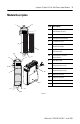
Compact 32-point 24V dc Sink/Source Input Module 3 Module Description 1 2a Item Description 1 bus lever (with locking function) 2a upper panel mounting tab 2b lower panel mounting tab 3 I/O diagnostic LEDs 4 module door with terminal identification label 5a movable bus connector with female pins 5b stationary bus connector with male pins 6 nameplate label 7a upper tongue-and-groove slots 7b lower tongue-and-groove slots 8a upper DIN rail latch 8b lower DIN rail latch 9 write-on
Compact 32-point 24V dc Sink/Source Input Module Module Installation Compact I/O is suitable for use in an industrial environment when installed in accordance with these instructions. Specifically, this equipment is intended for use in clean, dry environments (Pollution degree 2(1)) and to circuits not exceeding Over Voltage Category II(2) (IEC 60664-1).
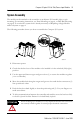
Compact 32-point 24V dc Sink/Source Input Module 5 System Assembly The module can be attached to the controller or an adjacent I/O module before or after mounting. For mounting instructions, see Panel Mounting on page 6, or DIN Rail Mounting on page 8. To work with a system that is already mounted, see Replacing a Single Module within a System on page 8. The following procedure shows you how to assemble the Compact I/O system. 3 4 2 1 6 1 5 30536-M 1. Disconnect power. 2.
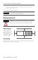
Compact 32-point 24V dc Sink/Source Input Module 7. Attach an end cap terminator (5) to the last module in the system by using the tongue-and-groove slots as before. 8. Lock the end cap bus terminator (6). IMPORTANT A 1769-ECR or 1769-ECL right or left end cap must be used to terminate the end of the serial communication bus. Mounting Expansion I/O During panel or DIN rail mounting of all devices, be sure that all debris (metal chips, wire strands, etc.) is kept from falling into the module.
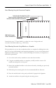
Compact 32-point 24V dc Sink/Source Input Module 7 Panel Mounting Using the Dimensional Template Host Controller Spacing for single-wide modules 35mm (1.378 in.) Spacing for one-and-a half-wide modules 52.5mm (2.067 in.) Refer to host controller documentation for this dimension. Note: Overall hole spacing tolerance: ±0.4mm (0.016 in.). 30535-M Locate holes every 17.5 mm (0.689 in.) to allow for a mix of single-wide and one-and-a-half-wide modules (e.g., 1769-OA16).
Compact 32-point 24V dc Sink/Source Input Module NOTE: If mounting more modules, mount only the last one of this group and put the others aside. This reduces remounting time during drilling and tapping of the next group. 7. Repeat steps 1 to 6 for any remaining modules. DIN Rail Mounting The module can be mounted using these DIN rails: 35 x 7.5 mm (EN 50 022 - 35 x 7.5) or 35 x 15 mm (EN 50 022 - 35 x 15). Before mounting the module on a DIN rail, close the DIN rail latches.
Compact 32-point 24V dc Sink/Source Input Module 9 Field Wiring Connections Grounding the Module This product is intended to be mounted to a well-grounded mounting surface such as a metal panel. Additional grounding connections from the module’s mounting tabs or DIN rail (if used), are not required unless the mounting surface cannot be grounded. Refer to Industrial Automation Wiring and Grounding Guidelines, Allen-Bradley publication 1770-4.1, for additional information.
Compact 32-point 24V dc Sink/Source Input Module A removable write-on label is included with the module. Remove the label from the door, mark the identification of each terminal with permanent ink, and slide the label back into the door. Your markings (ID tag) will be visible when the module door is closed.
Compact 32-point 24V dc Sink/Source Input Module 11 Simplified Input Circuit Diagram VCC ASIC Signal GND 31560-MC Wiring Options for the I/O Module Included with your 32-point I/O module is a keyed 40-pin female connector and crimp type pins. These components allow you to wire I/O devices to the module using a 40-conductor cable or individual wires. Refer to page 13 for connector/pin assembly instructions.
Compact 32-point 24V dc Sink/Source Input Module Option 2 - Using Allen-Bradley 1492 Wiring Systems Allen-Bradley 1492 wiring systems are available for connecting 32 point I/O modules to external I/O. These wiring systems include a pre-wired cable available in four lengths: 0.5m (1.6 feet), 1.0m (3.3 feet), 2.5m (8.2 feet), 5.0m (16.4 feet). An Interface Module for connecting external devices is also available. Cables are equipped with keyed connectors at both ends for proper connections.
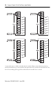
Compact 32-point 24V dc Sink/Source Input Module 13 Labeling for the 1492 Interface Module Several different stick-on label sets are provided on a single card with 1492 Interface Modules. Each label set is identified with an I/O module catalog number and words “upper” and “lower” to identify which terminal strip the label should be affixed to. The table on the following page identifies the 1769-IQ32T 32-point labels and their location on the interface module.
Compact 32-point 24V dc Sink/Source Input Module Assemble the Wire Contacts 1. Strip the wire insulation as shown in Figure 1. Crimp pins can accept 22 to 26 AWG wire. 2. Insert the wire up to the wire stop as shown in Figure 2. 3. Crimp with DDK crimp tool 357J-5538. Equivalent Amp part numbers are: pin #87666-2, connector - #102387-9, and crimp tool - #90418-1. Pins and connectors from different manufacturers cannot be assembled together. For example, Amp pins cannot be used with a DDK connector.
Compact 32-point 24V dc Sink/Source Input Module 15 I/O Memory Mapping Input Data File For each input module, slot x, words 0-1 in the input data file contain the current state of the field input points.
Compact 32-point 24V dc Sink/Source Input Module Spare/Replacement Module Parts • 1746-N3: Connector kit (1 connector, 40 terminals per kit) Specifications General Specifications Specification Value Dimensions 118 mm (height) x 87 mm (depth) x 35mm (width) height including mounting tabs is 138 mm 4.65 in (height) x 3.43 in (depth) x 1.38 in (width) height including mounting tabs is 5.43 in Approximate Shipping Weight (with carton) 230 g (0.
Compact 32-point 24V dc Sink/Source Input Module 17 Input Specifications Specification 1769-IQ32T Voltage Category 24V dc (sink/source(1)) Operating Voltage Range 20.4 to 26.4V dc at 60°C (140°F) Number of Inputs 32 Bus Current Draw (max.) 170 mA at 5V dc (0.85 W) Heat Dissipation 4.77 Total Watts (The Watts per point, plus the minimum Watts, with all points energized.
Compact 32-point 24V dc Sink/Source Input Module Hazardous Location Considerations This equipment is suitable for use in Class I, Division 2, Groups A, B, C, D or non-hazardous locations only. The following WARNING statement applies to use in hazardous locations. WARNING EXPLOSION HAZARD • Substitution of components may impair suitability for Class I, Division 2. • Do not replace components or disconnect equipment unless power has been switched off or the area is known to be non-hazardous.
Compact 32-point 24V dc Sink/Source Input Module 19 For More Information For Refer to this Document Pub. No. A more detailed description of how to install MicroLogix 1200 and MicroLogix 1764-RM001 and use your Compact I/O with MicroLogix 1500 Programmable Controllers User 1200 & 1500 programmable controller. Manual A more detailed description of how to install 1769-ADN DeviceNet Adapter User and use your Compact I/O with the Manual 1769-ADN DeviceNet Adapter.
Rockwell Automation Support Rockwell Automation provides technical information on the web to assist you in using its products. At http://support.rockwellautomation.com, you can find technical manuals, a knowledge base of FAQs, technical and application notes, sample code and links to software service packs, and a MySupport feature that you can customize to make the best use of these tools.