Installation Instructions Compact 32-point 24V dc Sink/Source Input Module Catalog Number 1769-IQ32 Use this document as a guide when installing a Compact™ 32-point 24V dc sink/source input module.
Compact 32-point 24V dc Sink/Source Input Module Important User Information Because of the variety of uses for the products described in this publication, those responsible for the application and use of these products must satisfy themselves that all necessary steps have been taken to assure that each application and use meets all performance and safety requirements, including any applicable laws, regulations, codes and standards.
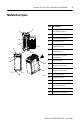
Compact 32-point 24V dc Sink/Source Input Module 3 Module Description Item Description 2a 1 3 WARNING -Do Not Remove RTB Unless Area is Non-Hazardous 10a IN 1 IN 3 IN 5 IN 7 10 10b IN 9 IN 11 IN 13 IN 15 DC COM IN 0 IN 2 IN 4 IN 6 DC COM IN 8 IN 10 IN 12 IN 14 bus lever (with locking function) 2a upper panel mounting tab 2b lower panel mounting tab 3 I/O diagnostic LEDs 4 module door with terminal identification label 5a movable bus connector with female pins 5b stationary bus connect
Compact 32-point 24V dc Sink/Source Input Module Module Installation Compact I/O is suitable for use in an industrial environment when installed in accordance with these instructions. Specifically, this equipment is intended for use in clean, dry environments (Pollution degree 2(1)) and to circuits not exceeding Over Voltage Category II(2) (IEC 60664-1).
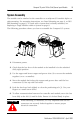
Compact 32-point 24V dc Sink/Source Input Module 5 System Assembly The module can be attached to the controller or an adjacent I/O module before or after mounting. For mounting instructions, see Panel Mounting on page 6, or DIN Rail Mounting on page 8. To work with a system that is already mounted, see Replacing a Single Module within a System on page 8. The following procedure shows you how to assemble the Compact I/O system. 3 4 2 1 6 1 5 30536-M 1. Disconnect power. 2.
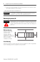
Compact 32-point 24V dc Sink/Source Input Module 7. Attach an end cap terminator (5) to the last module in the system by using the tongue-and-groove slots as before. 8. Lock the end cap bus terminator (6). IMPORTANT A 1769-ECR or 1769-ECL right or left end cap must be used to terminate the end of the serial communication bus. Mounting Expansion I/O ATTENTION ! During panel or DIN rail mounting of all devices, be sure that all debris (metal chips, wire strands, etc.
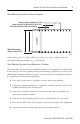
Compact 32-point 24V dc Sink/Source Input Module 7 Panel Mounting Using the Dimensional Template Host Controller Spacing for single-wide modules 35mm (1.378 in.) Spacing for one-and-a half-wide modules 52.5mm (2.067 in.) Refer to host controller documentation for this dimension. Note: Overall hole spacing tolerance: ±0.4mm (0.016 in.). 30535-M Locate holes every 17.5 mm (0.689 in.) to allow for a mix of single-wide and one-and-a-half-wide modules (e.g., 1769-OA16).
Compact 32-point 24V dc Sink/Source Input Module NOTE: If mounting more modules, mount only the last one of this group and put the others aside. This reduces remounting time during drilling and tapping of the next group. 7. Repeat steps 1 to 6 for any remaining modules. DIN Rail Mounting The module can be mounted using these DIN rails: 35 x 7.5 mm (EN 50 022 - 35 x 7.5) or 35 x 15 mm (EN 50 022 - 35 x 15). Before mounting the module on a DIN rail, close the DIN rail latches.
Compact 32-point 24V dc Sink/Source Input Module 9 8. Connect the modules together by locking (fully left) the bus levers on the replacement module and the right-side adjacent module. 9. Replace the mounting screws (or snap the module onto the DIN rail). Field Wiring Connections Grounding the Module This product is intended to be mounted to a well-grounded mounting surface such as a metal panel.
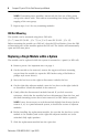
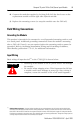
Compact 32-point 24V dc Sink/Source Input Module 1769-IQ32 +DC (Sinking) – DC (Sourcing) IN 0 IN 1 IN 2 IN 3 IN 7 24Vdc IN 4 IN 5 IN 6 DC COM 1 – DC (Sinking) + DC (Sourcing) + DC (Sinking) – DC (Sourcing) IN 9 24Vdc IN 11 IN 13 IN 15 DC COM 2 – DC (Sinking) + DC (Sourcing) IN 8 IN 10 IN 12 IN 14 +DC (Sinking) – DC (Sourcing) IN 16 IN 17 IN 18 IN 19 24Vdc IN 20 IN 21 IN 22 DC COM 3 IN 23 – DC (Sinking) + DC (Sourcing) + DC (Sinking) – DC (Sourcing) IN 25 24Vdc IN 27 IN 29 IN 31
Compact 32-point 24V dc Sink/Source Input Module 11 Removing the Finger-safe Terminal Block When wiring field devices to the module, it is not necessary to remove the terminal block. If you remove the terminal block, use the write-on label on the side of the terminal block to identify the module slot lcation and type. RTB position can be indicated by circling either the ‘R’ for right side or ‘L’ for left side. To remove the terminal block, loosen the upper and lower retaining screws.
Compact 32-point 24V dc Sink/Source Input Module Wire Size and Terminal Screw Torque Each terminal accepts as many as two wires with these restrictions: Wire Type Wire Size Terminal Screw Torque Retaining Screw Torque Solid Cu-90°C (194°F) #14 to #22 AWG 0.68 Nm (6 in-lbs) 0.46 Nm (4.1 in-lbs) Stranded Cu-90°C (194°F) #16 to #22 AWG 0.68 Nm (6 in-lbs) 0.46 Nm (4.
Compact 32-point 24V dc Sink/Source Input Module 13 Specifications General Specifications Specification Value Dimensions 118 mm (height) x 87 mm (depth) x 52.5 mm (width) height including mounting tabs is 138 mm 4.65 in. (height) x 3.43 in (depth) x 2.07 in (width) height including mounting tabs is 5.43 in. Approximate Shipping Weight (with carton) 440g (0.97 lbs.
Compact 32-point 24V dc Sink/Source Input Module Input Specifications Specification 1769-IQ32 Voltage Category 24V dc (sink/source ) Operating Voltage Range 10 to 30V dc at 30°C (86°F) 10 to 26.4V dc at 60°C (140°F) Number of Inputs 32 Bus Current Draw (max.) 170 mA at 5V dc (0.85W) Heat Dissipation 4.6 Total Watts (The Watts per point, plus the minimum Watts, with all points energized.) Signal Delay (max.) On Delay: 8.0 ms Off Delay: 8.0 ms Off-State Voltage (max.
Compact 32-point 24V dc Sink/Source Input Module 15 Hazardous Location Considerations This equipment is suitable for use in Class I, Division 2, Groups A, B, C, D or non-hazardous locations only. The following WARNING statement applies to use in hazardous locations. WARNING ! EXPLOSION HAZARD • Substitution of components may impair suitability for Class I, Division 2. • Do not replace components or disconnect equipment unless power has been switched off or the area is known to be non-hazardous.
For More Information For Refer to this Document Pub. No. A more detailed description of how to install MicroLogix 1200 and MicroLogix 1764-RM001B-US-P and use your Compact I/O with MicroLogix 1500 Programmable Controllers User 1200 & 1500 programmable controller. Manual A more detailed description of how to install 1769-ADN DeviceNet Adapter User and use your Compact I/O with the Manual 1769-ADN DeviceNet Adapter.