Installation Instructions Compact 16-point 24V dc Sink/Source High-speed Input Module Catalog Number 1769-IQ16F Use this document as a guide when installing a Compact™ 16-point 24V dc sink/source high-speed input module.
Compact 16-point 24V dc Sink/Source High-speed Input Module Important User Information Because of the variety of uses for the products described in this publication, those responsible for the application and use of these products must satisfy themselves that all necessary steps have been taken to assure that each application and use meets all performance and safety requirements, including any applicable laws, regulations, codes and standards.
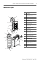
Compact 16-point 24V dc Sink/Source High-speed Input Module 3 Module Description Item Description 1 2a 3 DANGER Do Not Remove RTB Under Power Unless Area is Non-Hazardous 10a IN 1 IN 3 1 bus lever (with locking function) 2a upper panel mounting tab 2b lower panel mounting tab 3 I/O diagnostic LEDs 4 module door with terminal identification label 5a movable bus connector with female pins 5b stationary bus connector with male pins 6 nameplate label 7a upper tongue-and-groove slots 7
Compact 16-point 24V dc Sink/Source High-speed Input Module Module Installation Compact I/O is suitable for use in an industrial environment when installed in accordance with these instructions. Specifically, this equipment is intended for use in clean, dry environments (Pollution degree 2(1)) and to circuits not exceeding Over Voltage Category II(2) (IEC 60664-1).
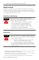
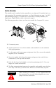
Compact 16-point 24V dc Sink/Source High-speed Input Module 5 System Assembly The module can be attached to the controller or an adjacent I/O module before or after mounting. For mounting instructions, see Panel Mounting on page 6, or DIN Rail Mounting on page 8. To work with a system that is already mounted, see Replacing a Single Module within a System on page 8. The following procedure shows you how to assemble the Compact I/O system. 3 4 2 1 6 1 5 1. Disconnect power. 2.
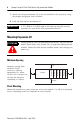
Compact 16-point 24V dc Sink/Source High-speed Input Module 7. Attach an end cap terminator (5) to the last module in the system by using the tongue-and-groove slots as before. 8. Lock the end cap bus terminator (6). IMPORTANT A 1769-ECR or 1769-ECL right or left end cap must be used to terminate the end of the serial communication bus. Mounting Expansion I/O ATTENTION ! During panel or DIN rail mounting of all devices, be sure that all debris (metal chips, wire strands, etc.
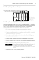
Compact 16-point 24V dc Sink/Source High-speed Input Module 7 Panel Mounting Using the Dimensional Template Right End Cap Compact I/O Compact I/O 122.6±0.2 (4.826±0.008) 28.5 (1.12) 35 (1.38) Compact I/O 132 (5.197) Host Controller For more than 2 modules: (number of modules - 1) X 35 mm (1.38 in.) Refer to host controller documentation for this dimension. NOTE: All dimensions are in mm (inches). Hole spacing tolerance: ±0.4 mm (0.016 in.
Compact 16-point 24V dc Sink/Source High-speed Input Module DIN Rail Mounting The module can be mounted using the following DIN rails: 35 x 7.5 mm (EN 50 022 - 35 x 7.5) or 35 x 15 mm (EN 50 022 - 35 x 15). Before mounting the module on a DIN rail, close the DIN rail latches. Press the DIN rail mounting area of the module against the DIN rail. The latches will momentarily open and lock into place.
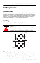
Compact 16-point 24V dc Sink/Source High-speed Input Module 9 Field Wiring Connections Grounding the Module This product is intended to be mounted to a well-grounded mounting surface such as a metal panel. Additional grounding connections from the module’s mounting tabs or DIN rail (if used), are not required unless the mounting surface cannot be grounded. Refer to Industrial Automation Wiring and Grounding Guidelines, Allen-Bradley publication 1770-4.1, for additional information.
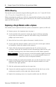
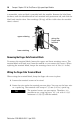
Compact 16-point 24V dc Sink/Source High-speed Input Module A removable, write-on label is provided with the module. Remove the label from the door, mark the identification of each terminal with permanent ink, and slide the label back into the door. Your markings (ID tag) will be visible when the module door is closed. upper retaining wiring the finger-safe terminal lower retaining Removing the Finger-Safe Terminal Block To remove the terminal block, loosen the upper and lower retaining screws.
Compact 16-point 24V dc Sink/Source High-speed Input Module 11 3. Tighten the terminal screw making sure the pressure plate secures the wire. Recommended torque when tightening terminal screws is 0.68 Nm (6 in-lbs). If you need to remove the finger-safe cover, insert a screw driver into one of the square, wiring holes and gently pry the cover off.
Compact 16-point 24V dc Sink/Source High-speed Input Module 1769-IQ16F Configuration File The read/writable configuration data file allows the setup of the digital filter settings for each of the two input groups. Group 0 is inputs 0 - 7, Group 1 is inputs 8 - 15. Word The manipulation of the bits from this file is normally done with programming software (e.g., RSLogix 500, RSNetworx for DeviceNet, etc.) during initial configuration of the system.
Compact 16-point 24V dc Sink/Source High-speed Input Module 13 Specifications General Specifications Specification Value Dimensions 118 mm (height) x 87 mm (depth) x 35 mm (width) height including mounting tabs is 138 mm 4.65 in. (height) x 3.43 in (depth) x 1.38 in (width) height including mounting tabs is 5.43 in. Approximate Shipping Weight (with carton) 270g (0.6 lbs.
Compact 16-point 24V dc Sink/Source High-speed Input Module Input Specifications Specification 1769-IQ16F Voltage Category 24V dc (sink/source(1)) Operating Voltage Range 10 to 30V dc at 30°C (86°F) 10 to 26.4V dc at 60°C (140°F) Number of Inputs 16 Bus Current Draw (max.) 110 mA at 5V dc (0.55W) Heat Dissipation 3.55 Total Watts (The Watts per point, plus the minimum Watts, with all points energized.
Compact 16-point 24V dc Sink/Source High-speed Input Module 15 Hazardous Location Considerations This equipment is suitable for use in Class I, Division 2, Groups A, B, C, D or non-hazardous locations only. The following ATTENTION statement applies to use in hazardous locations. ATTENTION EXPLOSION HAZARD – ! – – – – Substitution of components may impair suitability for Class I, Division 2.
For More Information For Refer to this Document Pub. No.