Compact™ 240V ac Input Module (Catalog Number 1769-IM12) Installation Instructions Inside Module Description ...................................................................2 Module Installation ....................................................................3 System Assembly......................................................................4 Mounting Expansion I/O............................................................5 Replacing a Single Module within a System .............................
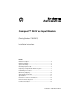
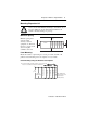
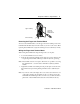
Compact™ 240V ac Input Module Module Description Ite m 1 2a 1 Description bus lever (with locking function) 2a upper panel mounting tab 3 2b lower panel mounting tab DANGER Do Not Remove RTB Under Power Unless Area is Non-Hazardous 10a IN 0 IN 1 IN 2 IN 3 3 I/O diagnostic LEDs 4 module door with terminal identification label IN 4 IN 5 IN 6 IN 7 IN 8 10 IN 9 IN 10 IN 11 NC NC movable bus connector 5a with female pins NC NC 10b AC COM AC COM Ensure Adjacent Bus Lever is Unlatched/L
Compact™ 240V ac Input Module 3 Module Installation Compact I/O is suitable for use in an industrial environment when installed in accordance with these instructions. Specifically, this equipment is intended for use in clean, dry environments (Pollution degree 21) and to circuits not exceeding Over Voltage Category II2 (IEC 60664-1).3 Prevent Electrostatic Discharge ! ATTENTION: Electrostatic discharge can damage integrated circuits or semiconductors if you touch bus connector pins.
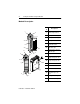
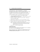
Compact™ 240V ac Input Module System Assembly The module can be attached to the controller or an adjacent I/O module before or after mounting. For mounting instructions, see “Panel Mounting” on page 5, or “DIN Rail Mounting” on page 6. To work with a system that is already mounted, see “Replacing a Single Module within a System” on page 7. The following procedure shows you how to assemble the Compact I/O system. 3 4 2 1 6 1 5 1. Disconnect power. 2.
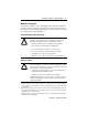
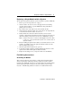
Compact™ 240V ac Input Module 5 Mounting Expansion I/O ! ATTENTION: During panel or DIN rail mounting of all devices, be sure that all debris (metal chips, wire strands, etc.) is kept from falling into the module. Debris that falls into the module could cause damage on power up. Minimum Spacing End Cap Compact I/O Compact I/O Compact I/O Controller Side Compact I/O Compact I/O Top Maintain spacing from enclosure walls, wireways, adjacent equipment, etc. Allow 50 mm (2 in.
Compact™ 240V ac Input Module Panel Mounting Procedure Using Modules as a Template The following procedure allows you to use the assembled modules as a template for drilling holes in the panel. If you have sophisticated panel mounting equipment, you can use the dimensional template provided on page 5. Due to module mounting hole tolerance, it is important to follow these procedures: 1. On a clean work surface, assemble no more than three modules. 2.
Compact™ 240V ac Input Module 7 Replacing a Single Module within a System The module can be replaced while the system is mounted to a panel (or DIN rail). 1. Remove power. See important note on page 3. 2. On the module to be removed, remove the upper and lower mounting screws from the module (or open the DIN latches using a flat-blade or phillips style screw driver). 3. Move the bus lever to the right to disconnect (unlock) the bus. 4.
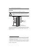
Compact™ 240V ac Input Module Input Wiring Basic wiring1 of input devices to the 1769-IM12 is shown below. ATTENTION: Be careful when stripping wires. Wire fragments that fall into a module could cause damage at power up. Once wiring is complete, ensure the module is free of all metal fragments. ! L1 IN 0 IN 1 IN 2 IN 3 IN 4 IN 5 IN 6 200/240V ac IN 7 IN 8 IN 9 IN 10 Note: Do not use the NC terminals as connection IN 11 NC NC NC NC L2 AC COM AC COM Commons are connected internally.
Compact™ 240V ac Input Module 9 upper retaining wiring the finger-safe terminal block lower retaining Removing the Finger-Safe Terminal Block To remove the terminal block, loosen the upper and lower retaining screws. The terminal block will back away from the module as you remove the screws. When replacing the terminal block, torque the retaining screws to 0.46 Nm (4.1 in-lbs). Wiring the Finger-Safe Terminal Block When wiring the terminal block, keep the finger-safe cover in place. 1.
Compact™ 240V ac Input Module Wire Size and Terminal Screw Torque Each terminal accepts up to two wires with the following restrictions: Wire Type Wire Size Terminal Screw Retaining Screw Torque Torque Solid Cu-90°C (194°F) #14 to #22 AWG 0.68 Nm (6 in-lbs) 0.46 Nm (4.1 in-lbs) Stranded Cu-90°C (194°F) #16 to #22 AWG 0.68 Nm (6 in-lbs) 0.46 Nm (4.
Compact™ 240V ac Input Module 11 Specifications General Specifications Specification Dimensions Value 118 mm (height) x 87 mm (depth) x 35 mm (width) height including mounting tabs is 138 mm 4.65 in. (height) x 3.43 in (depth) x 1.38 in (width) height including mounting tabs is 5.43 in. Approximate Shipping Weight (with carton) 300g (0.66 lbs.
Compact™ 240V ac Input Module Input Specifications Specification 1769-IM12 Voltage Category 200/240V ac Operating Voltage Range 159V ac to 265V ac at 47 Hz to 63 Hz Number of Inputs 12 Bus Current Draw (max.) 100 mA at 5V dc (0.500W) Heat Dissipation 3.65 Total Watts (The Watts per point, plus the minimum Watts, with all points energized.) Signal Delay (max.) On Delay: 20.0 ms Off Delay: 20.0 ms Off-State Voltage (max.) 40V ac Off-State Current (max.) 2.5 mA On-State Voltage (min.
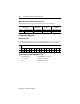
Compact™ 240V ac Input Module 13 Temperature Derating The following graph shows the number of points that can be ON at various ambient temperatures. Maximum Number of Points (Pts) ON 12 1769-IM12 Point Derating vs.
Compact™ 240V ac Input Module Hazardous Location Considerations This equipment is suitable for use in Class I, Division 2, Groups A, B, C, D or non-hazardous locations only. The following ATTENTION statement applies to use in hazardous locations. ATTENTION: EXPLOSION HAZARD ! • Substitution of components may impair suitability for Class I, Division 2. • Do not replace components or disconnect equipment unless power has been switched off or the area is known to be nonhazardous.
Compact™ 240V ac Input Module 15 For More Information For Refer to this Document Pub. No. A more detailed description of how to install and use your Compact I/O with MicroLogix 1200 & 1500 programmable controller. MicroLogix 1200 and MicroLogix 1500 Programmable Controllers User Manual 1764-RM001B-US-P A more detailed description of how to install and use your Compact I/O with the 1769-ADN DeviceNet Adapter.
Compact and MicroLogix are trademarks of Rockwell Automation. Publication 1769-IN011B-EN-P - June 2000 Supercedes 1769-IN011A-EN-P - April 2000 & 1769-5.8 - January 1999 PN 40071-096-01(B) © 2000 Rockwell International Corporation. All rights reserved. Printed in the U.S.A.