Installation Instructions Compact I/O 1769-IF8 Analog Input Module Inside Module Description ..................................................................................2 Module Installation...................................................................................3 System Assembly......................................................................................4 Mounting Expansion I/O ...........................................................................
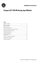
Compact I/O 1769-IF8 Analog Input Module Module Description Item Description 1 bus lever (with locking function) 2a upper panel mounting tab 2b lower panel mounting tab 3 module status LED 4 module door with terminal identification label 5a movable bus connector with female pins 5b stationary bus connector with male pins 6 nameplate label 7a upper tongue-and-groove slots 7b lower tongue-and-groove slots 8a upper DIN rail latch 8b lower DIN rail latch 9 write-on label (user ID t
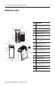
Compact I/O 1769-IF8 Analog Input Module 3 Module Installation Compact I/O is suitable for use in an industrial environment when installed in accordance with these instructions. Specifically, this equipment is intended for use in clean, dry environments (Pollution degree 2(1)) and to circuits not exceeding Over Voltage Category II(2) (IEC 60664-1).
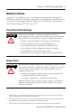
Compact I/O 1769-IF8 Analog Input Module System Assembly The module can be attached to the controller or an adjacent I/O module before or after mounting. For mounting instructions, see “Panel Mounting” on page 6, or “DIN Rail Mounting” on page 7. To work with a system that is already mounted, see “Replacing a Single Module within a System” on page 7. The following procedure shows you how to assemble the Compact I/O system. 3 4 2 1 6 1 5 30536-M 1. Disconnect power. 2.
Compact I/O 1769-IF8 Analog Input Module 5 6. To allow communication between the controller and module, move the bus lever fully to the left (4) until it clicks. Ensure it is locked firmly in place. ATTENTION When attaching I/O modules, it is very important that the bus connectors are securely locked together to ensure proper electrical connection. 7. Attach an end cap terminator (5) to the last module in the system by using the tongue-and-groove slots as before. 8. Lock the end cap bus terminator (6).
Compact I/O 1769-IF8 Analog Input Module Panel Mounting Mount the module to a panel using two screws per module. Use M4 or #8 panhead screws. Mounting screws are required on every module. Panel Mounting Using the Dimensional Template NOTE: Overall hole spacing tolerance: ±0.4 mm (0.016 in.) Locate holes every 17.5 mm (0.689 in) to allow for a mix of single-wide and one-and-a-half-wide modules (e.g., 1769-OA16). Host Controller Spacing for single-wide modules 35 mm (1.378 in). l Mountingmodules 52.
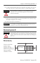
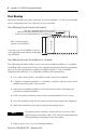
Compact I/O 1769-IF8 Analog Input Module 7 DIN Rail Mounting The module can be mounted using the following DIN rails: 35 x 7.5 mm (EN 50 022 - 35 x 7.5) or 35 x 15 mm (EN 50 022 - 35 x 15). Before mounting the module on a DIN rail, close the DIN rail latches. Press the DIN rail mounting area of the module against the DIN rail. The latches will momentarily open and lock into place. Replacing a Single Module within a System The module can be replaced while the system is mounted to a panel (or DIN rail).
Compact I/O 1769-IF8 Analog Input Module Module Spare/Replacement Parts • Terminal block, catalog number 1769-RTBN18 (1 per kit) Field Wiring Connections Grounding the Module This product is intended to be mounted to a well-grounded mounting surface such as a metal panel. Additional grounding connections from the module’s mounting tabs or DIN rail (if used), are not required unless the mounting surface cannot be grounded.
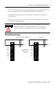
Compact I/O 1769-IF8 Analog Input Module 9 • The 1769-IF8 module does not provide loop power for analog inputs. Use a power supply that matches the input transmitter specifications. • Differential analog inputs are more immune to noise than single-ended analog inputs. • Voltages on Vin+, V/Iin-, and Iin+ of the 1769-IF8 module must be within ±10V dc of analog common. ATTENTION Be careful when stripping wires. Wire fragments that fall into a module could cause damage at power up.
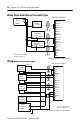
Compact I/O 1769-IF8 Analog Input Module Wiring Single-Ended Sensor/Transmitter Types 1769-IF8 Terminal Block Sensor/Trans + mitter Supply(1) V in 0 + Current Transmitter + Signal V/I in 0 I in 0 + ANLG Com V in 1 + V/I in 1 - Voltage Transmitter + Ground I in 1 + ANLG Com Signal V in 2 + V/I in 2 I in 2 + ANLG Com Voltage Transmitter + Ground V in 3 + Signal V/I in 3 I in 3 + ANLG Com NC 1 The sensor power supply must be rated Class 2. NC Wiring for channels 4-7 are identical.
Compact I/O 1769-IF8 Analog Input Module 11 Labeling the Terminals A removable, write-on label is provided with the module. Remove the label from the door, mark the identification of each terminal with permanent ink, and slide the label back into the door. Your markings (ID tag) will be visible when the module door is closed.
Compact I/O 1769-IF8 Analog Input Module Wiring the Finger-Safe Terminal Block When wiring the terminal block, keep the finger-safe cover in place. 1. Loosen the terminal screws to be wired. 2. Route the wire under the terminal pressure plate. You can use the bare wire or a spade lug. The terminals will accept a 6.35 mm (0.25 in.) spade lug. The terminal screws are non-captive. Therefore, it is possible to use a ring lug [maximum 1/4 inch o.d. with a 0.139 inch minimum i.d. (M3.5)] with the module.
Compact I/O 1769-IF8 Analog Input Module 13 I/O Memory Mapping IMPORTANT If you are using RSLogix 5000, version 15, please refer to RSLogix 5000, Version 15, Controller Tags on page 18. Input Data File Word For each input module, slot x, words 0-7 in the input data file contain the analog values of the inputs.
Compact I/O 1769-IF8 Analog Input Module Output Data File Word For each input module, slot x, word 0 in the output data file contains alarm unlatch control bits. 0 Bit Position 15 14 13 12 11 10 9 8 7 6 5 4 3 2 1 0 CL(1) CL(2) L7 H7 CL L6 CL H6 CL L5 CL H5 CL L4 CL H4 CL L3 CL H3 CL L2 CL H2 CL L1 CL H1 CL L0 CL H0 (1) CL Lx = Cancel Low Process Alarm Latch x. This lets you individually cancel each low process alarm latch. Cancel = 1.
Compact I/O 1769-IF8 Analog Input Module 15 Configuration Data File Word The manipulation of the bits from this file is normally done with programming software (e.g. RSLogix 500, RSNetworx for DeviceNet, etc.) during initial configuration of the system. In that case, graphical screens are provided by the programmer to simplify configuration. However, some systems, like the 1769-ADN DeviceNet Adapter, also allow the bits to be altered as part of the control program, using communication rungs.
Compact I/O 1769-IF8 Analog Input Module Bit Position Word 16 15 27 14 13 12 Reserved 11 10 9 8 7 Inpt Dta Fm Chl4 6 5 4 Reserved 28 S Process Alarm High Data Value Channel 4 29 S Process Alarm Low Data Value Channel 4 30 S Alarm Dead Band Value Channel 4 31 3 2 1 0 Inpt Tp/RngeSel Chl4 Pad 32 EC 33 Reserved Reserved EA AL EI Reserved Input Filter Sel Chl5 Inpt Dta Fm Chl5 Reserved Inpt Tp/RngeSel Chl5 34 S Process Alarm High Data Value Channel 5 35 S Pro
Compact I/O 1769-IF8 Analog Input Module Define To Select Input Filter Selection/ -3 dB Frequency 60 Hz 50 Hz 10 Hz 250 Hz 500 Hz Enable Disable Enable Disable Enable Disable Enable Interrupt Process Alarm Latch Enable Process Alarms Enable Channel Define Enable Disable Make these bit settings 15 14 13 12 11 9 8 7-4 3 0 0 0 0 0 2 0 0 0 0 1 1 0 0 1 1 0 0 0 1 0 1 0 1 0 1 0 1 0 1 0 Indicate this 15-11 -10 to +10V dc 0 to 5V dc 0 to 10V dc 4 to 20 mA 1 to 5V dc 0 to 20 mA Input Data Raw/Proport
Compact I/O 1769-IF8 Analog Input Module RSLogix 5000, Version 15, Controller Tags Use the following controller tags with RSLogix 5000, version 15. Channel 0 and 1 Configuration Data Channel 0 and 1 configuration data is shown below. The same information applies to all channels. - Local:1:C AB:1769_IF8:C:0 + Local:1:C.RTSInterval INT Decimal Local:1:C.RTSEn BOOL Decimal Local:1:C.Ch0Filter SINT Decimal Local:1:C.Ch0AlarmInterruptEn BOOL Decimal Local:1:C.
Compact I/O 1769-IF8 Analog Input Module Tag Name To Select Ch#Filter 60 Hz 50 Hz 10 Hz 250 Hz 500 Hz Enable Disable Enable Disable Enable Disable Enable Disable -10…+10V dc 0…5V dc 0…10V dc 4…20 mA 1…5V dc 0…20 mA Raw/proportional counts Engineering units Scaled for PID Percent range Ch#AlarmInterruptEn Ch#AlarmLatchEn Ch#AlarmEn Ch#En Ch#Range Ch#DataFormat (1) Make These Bit Settings(1) 15-8 7 6 5 4 3 2 0 0 0 0 1 1 0 0 1 1 0 0 0 0 0 1 1 0 0 1 1 0 0 0 0 0 1 0 1 0 1 0 1 0 1 0 1 0 0 1 0 1 0 1
Compact I/O 1769-IF8 Analog Input Module Input Data - Local:1:I AB:1769_IF8:I:0 + Local:1:I.Fault DINT Binary + Local:1:I.Ch0Data INT Decimal + Local:1:I.Ch1Data INT Decimal + Local:1:I.Ch2Data INT Decimal + Local:1:I.Ch3Data INT Decimal + Local:1:I.Ch4Data INT Decimal + Local:1:I.Ch5Data INT Decimal + Local:1:I.Ch6Data INT Decimal + Local:1:I.Ch7Data INT Decimal + Local:1:I.RealTimeSample INT Decimal + Local:1:I.CombinedStatus SINT Binary Local:1:I.
Compact I/O 1769-IF8 Analog Input Module + + + Local:1:I.Ch2_3Status SINT Binary Local:1:I.Ch2OverRange BOOL Decimal Local:1:I.Ch2UnderRange BOOL Decimal Local:1:I.Ch2HAlarm BOOL Decimal Local:1:I.Ch2LAlarm BOOL Decimal Local:1:I.Ch3OverRange BOOL Decimal Local:1:I.Ch3UnderRange BOOL Decimal Local:1:I.Ch3HAlarm BOOL Decimal Local:1:I.Ch3LAlarm BOOL Decimal Local:1:I.Ch4_5Status SINT Binary Local:1:I.Ch4OverRange BOOL Decimal Local:1:I.
Compact I/O 1769-IF8 Analog Input Module Tag Name Bit Indicates This Combined Status Ch7 Status Ch6 Status Ch5 Status Ch4 Status Ch3 Status Ch2 Status Ch1 Status Ch0 Status Ch0_1 Status Ch1 LAlarm Ch1 HAlarm Ch1 Under Range Ch1 Over Range Ch0 LAlarm Ch0 HAlarm Ch0 Under Range Ch0 Over Range Ch2_3 Status Ch3 LAlarm Ch3 HAlarm Ch3 Under Range Ch3 Over Range Ch2 LAlarm Ch2 HAlarm Ch2 Under Range Ch2 Over Range Ch4_5 Status Ch5 LAlarm Ch5 HAlarm Ch5 Under Range Ch5 Over Ran
Compact I/O 1769-IF8 Analog Input Module 23 Output Data - Local:1:O AB:1769_IF8:O:0 + Local:1:O.AlarmUnlatch INT Binary Local:1:O.Ch0HAlarmUnlatch BOOL Decimal Local:1:O.Ch0LAlarmUnlatch BOOL Decimal Local:1:O.Ch1HAlarmUnlatch BOOL Decimal Local:1:O.Ch1LAlarmUnlatch BOOL Decimal Local:1:O.Ch2HAlarmUnlatch BOOL Decimal Local:1:O.Ch2LAlarmUnlatch BOOL Decimal Local:1:O.Ch3HAlarmUnlatch BOOL Decimal Local:1:O.Ch3LAlarmUnlatch BOOL Decimal Local:1:O.
Compact I/O 1769-IF8 Analog Input Module Specifications General Specifications Specification Value Dimensions 118 mm (height) x 87 mm (depth) x 52.5 mm (width) height including mounting tabs is 138 mm 4.65 in. (height) x 3.43 in (depth) x 2.07 in (width) height including mounting tabs is 5.43 in. Approximate Shipping Weight (with carton) 450g (0.99 lbs.
Compact I/O 1769-IF8 Analog Input Module 25 Input Specifications Specification 1769-IF8 Analog Normal Operating Voltage: ± 10V dc, 0 to 10V dc, 0 to 5V dc, 1 to 5V dc Current: 0 to 20 mA, 4 to 20 mA Ranges(1) Full Scale Analog Ranges(1) Voltage: ± 10.5V dc, 0 to 10.5V dc, 0 to 5.25V dc, 0.5 to 5.25V dc Current: 0 to 21 mA, 3.2 to 21 mA Number of Inputs 8 differential or single-ended Bus Current Draw (max.) 120 mA at 5V dc 70 mA at 24V dc Heat Dissipation 3.
Compact I/O 1769-IF8 Analog Input Module Specification 1769-IF8 Accuracy Drift with Temperature Voltage Terminal: ±0.003% per °C Current Terminal: ±0.0045% per °C Calibration The module performs autocalibration on channel enable and on a configuration change between channels. Non-linearity (in percent full scale) ±0.03% Repeatability(1) ±0.03% Module Error over Full Temperature Range (0 to +60°C [+32°F to +140°F]) Voltage: ±0.
Compact I/O 1769-IF8 Analog Input Module 27 Hazardous Location Considerations This equipment is suitable for use in Class I, Division 2, Groups A, B, C, D or non-hazardous locations only. The following ATTENTION statement applies to use in hazardous locations. WARNING EXPLOSION HAZARD • Substitution of components may impair suitability for Class I, Division 2. • Do not replace components or disconnect equipment unless power has been switched off or the area is known to be non-hazardous.
Compact I/O 1769-IF8 Analog Input Module For More Information For Refer to this Document Pub. No. A more detailed description of how to install MicroLogix 1500 Programmable and use your Compact I/O with MicroLogix 1500 Controllers User Manual programmable controller. 1764-UM001 Detailed information on installing, programming, and troubleshooting your Compact Analog I/O modules.
Compact I/O 1769-IF8 Analog Input Module 29 Notes: Publication 1769-IN067B-EN-P - September 2005
Compact I/O 1769-IF8 Analog Input Module Notes: Publication 1769-IN067B-EN-P - September 2005
Compact I/O 1769-IF8 Analog Input Module 31 Notes: Publication 1769-IN067B-EN-P - September 2005
Rockwell Automation Support Rockwell Automation provides technical information on the web to assist you in using our products. At http://support.rockwellautomation.com, you can find technical manuals, a knowledge base of FAQs, technical and application notes, sample code and links to software service packs, and a MySupport feature that you can customize to make the best use of these tools.