Installation Instructions Compact™ Combination Analog I/O Module (Catalog Number 1769-IF4XOF2) Inside Module Description ..................................................................................2 Module Installation...................................................................................3 System Assembly......................................................................................4 Mounting Expansion I/O ..........................................................................
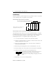
Compact™ Combination Analog I/O Module Module Description The 1769-IF4XOF2 module features 4 analog input points and 2 analog output points, with input and output ranges of 0 to 10V dc and 0 to 20 mA, with 8-bit resolution.
Compact™ Combination Analog I/O Module 3 Module Installation Compact I/O is suitable for use in an industrial environment when installed in accordance with these instructions. Specifically, this equipment is intended for use in clean, dry environments (Pollution degree 2(1)) and to circuits not exceeding Over Voltage Category II (2) (IEC 60664-1).
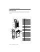
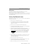
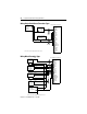
Compact™ Combination Analog I/O Module System Assembly The module can be attached to the controller or an adjacent I/O module before or after mounting. For mounting instructions, see “Panel Mounting” on page 6, or “DIN Rail Mounting” on page 7. To work with a system that is already mounted, see “Replacing a Single Module within a System” on page 7. The following procedure shows you how to assemble the Compact I/O system. C D B A F A E 1. Disconnect power. 2.
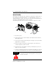
Compact™ Combination Analog I/O Module 5 7. Attach an end cap terminator (E) to the last module in the system by using the tongue-and-groove slots as before. 8. Lock the end cap bus terminator (F). IMPORTANT A 1769-ECR or 1769-ECL right or left end cap must be used to terminate the end of the communication bus. Mounting Expansion I/O ATTENTION ! During panel or DIN rail mounting of all devices, be sure that all debris (metal chips, wire strands, etc.) is kept from falling into the module.
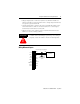
Compact™ Combination Analog I/O Module Panel Mounting Mount the module to a panel using two screws per module. Use M4 or #8 panhead screws. Mounting screws are required on every module. Panel Mounting Using the Dimensional Template For more than 2 modules: (number of modules-1) X 35mm (1.38 in.) End Cap Compact I/O 122.6±0.2 (4.826±0.008) 28.5 (1.12) Compact I/O NOTE: All dimensions are in mm (inches). Hole spacing tolerance: ±0.4 mm (0.016 in.) Host Controller 132 (5.197) Compact I/O 35 (1.
Compact™ Combination Analog I/O Module 7 DIN Rail Mounting The module can be mounted using the following DIN rails: 35 x 7.5 mm (EN 50 022 - 35 x 7.5) or 35 x 15 mm (EN 50 022 - 35 x 15). Before mounting the module on a DIN rail, close the DIN rail latches. Press the DIN rail mounting area of the module against the DIN rail. The latches will momentarily open and lock into place. Replacing a Single Module within a System The module can be replaced while the system is mounted to a panel (or DIN rail).
Compact™ Combination Analog I/O Module Module Spare/Replacement Parts • Terminal block, catalog number 1769-RTBN18 (1 per kit) • Door, catalog number 1769-RD (2 per kit) Field Wiring Connections Grounding the Module This product is intended to be mounted to a well-grounded mounting surface such as a metal panel. Additional grounding connections from the module’s mounting tabs or DIN rail (if used), are not required unless the mounting surface cannot be grounded.
Compact™ Combination Analog I/O Module 9 • Voltage outputs (Vout 0+ and Vout 1+) of the 1769-IF4XOF2 module are referenced to ANLG COM. Load resistance for a voltage output channel must be equal to or greater than 1K Ω. • Current outputs (Iout 0+ and Iout 1+) of the 1769-IF4XOF2 module source current that returns to ANLG COM. Load resistance for a current output channel must remain between 0 and 300 Ω.
Compact™ Combination Analog I/O Module Wiring Single-Ended Sensor/Transmitter Types Sensor/ Transmitter Power Supply(1) 1769-IF4XOF2 Terminal Block + - Current Transmitter + Signal V in 0+ I in 0+ V/I in 0 V in 1+ I in 1+ V/I in 1- Voltage Transmitter V in 2+ + I in 2+ Ground Signal V/I in 2V in 3+ I in 3+ V/I in 3ANLG Com ANLG Com V out 0+ I out 0+ V out 1+ (1) The sensor power supply must be rated Class 2.
Compact™ Combination Analog I/O Module 11 Wiring Analog Outputs V in 0+ I in 0+ V/I in 0 V in 1+ I in 1+ V/I in 1V in 2+ I in 2+ V/I in 2V in 3+ I in 3+ Voltage Load V/I in 3- earth ground ANLG Com ANLG Com V out 0+ I out 0+ V out 1+ Current Load I out 1 + earth ground ATTENTION ! Analog outputs may fluctuate for less than a second when power is applied or removed. This characteristic is common to most analog outputs.
Compact™ Combination Analog I/O Module Labeling the Terminals A removable, write-on label is provided with the module. Remove the label from the door, mark the identification of each terminal with permanent ink, and slide the label back into the door. Your markings (ID tag) will be visible when the module door is closed. Removing the Finger-Safe Terminal Block When wiring field devices to the module, it is not necessary to remove the terminal block.
Compact™ Combination Analog I/O Module 13 Wiring the Finger-Safe Terminal Block When wiring the terminal block, keep the finger-safe cover in place. 1. Loosen the terminal screws to be wired. 2. Route the wire under the terminal pressure plate. You can use the bare wire or a spade lug. The terminals will accept a 6.35 mm (0.25 in.) spade lug. TIP The terminal screws are non-captive. Therefore, it is possible to use a ring lug [maximum 1/4 inch o.d. with a 0.139 inch minimum i.d. (M3.5)] with the module.
Compact™ Combination Analog I/O Module I/O Memory Mapping Input Data File The input data file provides access to input data for use in the control program, over-range indication for the input and output channels, and output data feedback as described below.
Compact™ Combination Analog I/O Module 15 The bits are defined as follows: • SGN = Sign bit in two’s complement format. Always positive (equal to zero) for the 1769-IF4XOF2 module. • Ix = Over-range flag bits for input channels 0 through 3. These bits can be used in the control program for error detection. When set to 1, the bits signal that the input signal is outside the normal operating range. However, the module continues to convert analog data to the maximum full-range value.
Compact™ Combination Analog I/O Module Output Data File The output data file applies only to output data from the module as shown in the table below. Word Bit Position 15 0 SGN Analog Output Data Channel 0 0 0 0 0 0 0 0 1 SGN Analog Output Data Channel 1 0 0 0 0 0 0 0 14 IMPORTANT 13 12 11 10 9 8 7 6 5 4 3 2 1 0 Bits 0 through 6 and Bit 15 of output data words 0 and 1 should always be set to zero in your control program.
Compact™ Combination Analog I/O Module 17 Configuration Data File Word The manipulation of the bits from this file is normally done with programming software (e.g. RSLogix 500, RSNetworx for DeviceNet, etc.) during initial configuration of the system. In that case, graphical screens are typically provided by the programmer to simplify configuration. However, some systems, like the 1769-ADN DeviceNet Adapter, also allow the bits to be altered as part of the control program, using communication rungs.
Compact™ Combination Analog I/O Module Hold Last State (0) – When reset, this bit directs the module to hold the analog output at the last converted value when the module transitions to Program Mode. This is the default condition. User-Defined Safe State (1) – When this bit is set and the module transitions to Program mode, the module converts the user-specified integer value from the Channel x Program Value Word (3 or 5) to the appropriate analog output for the configured range as wired.
Compact™ Combination Analog I/O Module 19 Specifications General Specifications Specification 1769-IF4XOF2 Dimensions 118 mm (height) x 87 mm (depth) x 35 mm (width) height including mounting tabs is 138 mm 4.65 in. (height) x 3.43 in (depth) x 1.38 in (width) height including mounting tabs is 5.43 in. Approximate Shipping Weight (with carton) 290g (0.64 lbs.
Compact™ Combination Analog I/O Module Specification 1769-IF4XOF2 Electrical /EMC: The module has passed testing at the following levels: (1) ESD Immunity (IEC61000-4-2) • 4 kV contact, 8 kV air, 4 kV indirect Radiated Immunity (IEC61000-4-3) • 10 V/m , 80 to 1000 MHz, 80% amplitude modulation, +900 MHz keyed carrier Fast Transient Burst (IEC61000-4-4) • 2 kV, 5kHz Surge Immunity (IEC61000-4-5) • 1 kV galvanic gun Conducted Immunity (IEC61000-4-6) • 10 V, 0.
Compact™ Combination Analog I/O Module Input Specification 1769-IF4XOF2 Maximum Overload at Input Terminals(6) Voltage Terminal: 20V continuous, 0.1 mA Current Terminal: 32 mA continuous, +5V dc Input Group to Bus Isolation 500V ac or 710V dc for 1 minute (qualification test) 30V ac/30V dc working voltage (IEC Class 2 reinforced insulation) Channel Diagnostics Over-range by bit reporting 21 (1) The over-range flag will come on when the normal operating range is exceeded.
Compact™ Combination Analog I/O Module Output Specification 1769-IF4XOF2 Output Ripple(3) ±0.05% range 0 to 50 kHz (referred to output range) Non-linearity (in percent full scale) ±0.4% Repeatability(4) ±0.05% (in percent full scale) Output Impedance 10 Ω (nominal) Open and Short-Circuit Protection Yes Maximum Short-Circuit Current: 40 mA Maximum Open Circuit Voltage: 15V Output Response at System Power Up and Power Down +2.0V dc to -1.
Compact™ Combination Analog I/O Module 23 Hazardous Location Considerations This equipment is suitable for use in Class I, Division 2, Groups A, B, C, D or non-hazardous locations only. The following WARNING statement applies to use in hazardous locations. WARNING ! EXPLOSION HAZARD • Substitution of components may impair suitability for Class I, Division 2. • Do not replace components or disconnect equipment unless power has been switched off or the area is known to be non-hazardous.
For More Information For Refer to this Document Pub. No. A more detailed description of how to install MicroLogix 1500 Programmable and use your Compact I/O with MicroLogix 1500 Controllers User Manual programmable controller. 1764-UM001A-US-P Detailed information on how to install and use your Compact I/O with the CompactLogix™ System. CompactLogix System User Manual 1769-UM007C-EN-P Detailed information on installing, programming, and troubleshooting your Compact Combination Analog I/O module.