Compact™ 8-Bit Low Resolution Analog I/O Combination Module (Catalog Number 1769-IF4XOF2) User Manual
Important User Information Because of the variety of uses for the products described in this publication, those responsible for the application and use of this control equipment must satisfy themselves that all necessary steps have been taken to assure that each application and use meets all performance and safety requirements, including any applicable laws, regulations, codes and standards.
Table of Contents Preface Who Should Use This Manual . . . . . . . . . . . . . . How to Use This Manual . . . . . . . . . . . . . . . . . . Manual Contents . . . . . . . . . . . . . . . . . . . . . Related Documentation . . . . . . . . . . . . . . . . . . . Conventions Used in This Manual . . . . . . . . . . . Rockwell Automation Support . . . . . . . . . . . . . . Local Product Support . . . . . . . . . . . . . . . . . Technical Product Assistance . . . . . . . . . . . .
Table of Contents ii Field Wiring Connections . . . . . . . . . . . . . . . Grounding. . . . . . . . . . . . . . . . . . . . . . . . System Wiring Guidelines. . . . . . . . . . . . . Removing the Finger-Safe Terminal Block. Wiring the Finger-Safe Terminal Block . . . Analog Input Wiring . . . . . . . . . . . . . . . . . . Terminal Door Label . . . . . . . . . . . . . . . . Analog Output Wiring . . . . . . . . . . . . . . . . . . . . . . . . . . . . . . . . . . . . . . . . . . . . . . . . . . . . . .
Table of Contents iii Appendix A Specifications General Specifications . . . . . . . . . . . . . . . . . . . . . . . . . . . . A-1 Input Specifications. . . . . . . . . . . . . . . . . . . . . . . . . . . . . . A-2 Output Specifications . . . . . . . . . . . . . . . . . . . . . . . . . . . . A-3 Appendix B Module Addressing and Configuration with MicroLogix 1500 Module Addressing . . . . . . . . . . . . . . . . . . . . . . . . . . . . 1769-IF4XOF2 Input Image. . . . . . . . . . . . . . . . . . . .
Table of Contents iv Publication 1769-UM008A-EN-P - November 2001
Preface Read this preface to familiarize yourself with the rest of the manual. This preface covers the following topics: • • • • • Who Should Use This Manual on page P-1 How to Use This Manual on page P-1 Related Documentation on page P-2 Conventions Used in This Manual on page P-2 Rockwell Automation Support on page P-3 Who Should Use This Manual Use this manual if you are responsible for designing, installing, programming, or troubleshooting control systems that use Allen-Bradley Compact™ I/O.
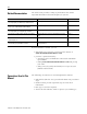
P-2 Related Documentation The table below provides a listing of publications that contain important information about MicroLogix 1500 systems. For Read this document Document number A user manual containing information on how to install, MicroLogix™ 1500 User Manual use and program your MicroLogix 1500 controller. 1764-UM001A-US-P A user manual containing information on how to install, DeviceNet Adapter User Manual and use your 1769-ADN DeviceNet Adapter.
P-3 Rockwell Automation Support Rockwell Automation offers support services worldwide, with over 75 Sales/Support Offices, 512 authorized distributors and 260 authorized Systems Integrators located throughout the United States alone, plus Rockwell Automation representatives in every major country in the world.
P-4 Publication 1769-UM008A-EN-P - November 2001
Chapter 1 Overview This chapter explains how analog data is used and describes the 1769-IF4XOF2 combination analog I/O module. Included is information about: • How to Use Analog I/O on page 1-1 • General Description of the Module’s Hardware and Diagnostic Features on page 1-2 • Overview of the Analog System on page 1-4 How to Use Analog I/O Analog refers to the representation of numerical quantities by the measurement of continuous physical variables. Analog applications are present in many forms.
1-2 Overview General Description of the Module’s Hardware and Diagnostic Features The analog input channels convert and digitally store analog data for retrieval by controllers, such as the MicroLogix™ 1500 and CompactLogix, and from network adapters like the 1769-ADN (Series B) DeviceNet Adapter. The module supports connections from any combination of up to four voltage or current analog sensors. The four high-impedance input channels can be wired as either single-ended or differential inputs.
Overview 1-3 The following illustration shows the hardware features of the Compact combination analog I/O module.
1-4 Overview General Diagnostic Features The module contains diagnostic features that can help you identify the source of problems that may occur during power-up or during normal channel operation. These power-up and channel diagnostics are explained in Chapter 5, Module Diagnostics and Troubleshooting. Overview of the Analog System The module communicates to the controller through the bus interface. The module also receives 5 and 24V dc power through the bus interface.
Overview 1-5 System Operation At power-up, the module performs a check of its internal circuits, memory, and basic functions. During this time, the module status LED remains off. If no faults are found during power-up diagnostics, the module status LED is turned on. After power-up checks are complete, the module waits for valid channel configuration data. If an invalid configuration is detected, the module generates a configuration error.
1-6 Overview Module Operation Module Block Diagram The module’s input channel circuitry consists of four differential analog inputs multiplexed into a single analog-to-digital (A/D) converter. The A/D converter reads the selected input signal and converts it to a digital value which is presented to the controller. The multiplexer sequentially switches each input channel to the module’s A/D converter.
Chapter 2 Quick Start for Experienced Users Before You Begin This chapter can help you to get started using the analog module. We base the procedures here on the assumption that you have an understanding of Allen-Bradley controllers. You should understand electronic process control and be able to interpret the ladder logic instructions required to generate the electronic signals that control your application.
2-2 Quick Start for Experienced Users What You Need To Do This chapter covers: • Verify power supply is adequate on page 2-2 • Attach and lock the module. on page 2-2 • Mount the I/O bank. on page 2-3 • Wire the module. on page 2-4 • Configure the module on page 2-5 • Start the system. on page 2-6 • Monitor the module status.
Quick Start for Experienced Users 2-3 e. To allow communication between the controller and module, move the bus lever fully to the left until it clicks. Ensure it is locked firmly in place. ATTENTION ! When attaching I/O modules, it is very important that the bus connectors are securely locked together to ensure proper electrical connection. f. Attach an end cap terminator to the last module in the system by using the tongue-and-groove slots as before. g. Lock the end cap bus terminator.
2-4 Quick Start for Experienced Users Step 4: Wire the module. Reference Chapter 3 (Installation and Wiring) The terminal connections are shown below: DANGER Do Not Remove RTB Under Power Unless Area is Non-Hazardous.
Quick Start for Experienced Users Configure the module Step 5: 2-5 Reference Chapter 4 (Module Data, Status, and Configuration Channel for 1769-IF4XOF2) The 1769-IF4XOF2 module is configured for current or voltage operation by proper wiring of the analog I/O device to the module. However, a channel is enabled using its configuration file. Table 2.
2-6 Quick Start for Experienced Users Step 6: Start the system. Reference Chapter 5 (Module Diagnostics and Troubleshooting) a. Apply power. b. Download your program, which contains the analog module configuration settings, to the controller and put the controller into Run mode. c. During a normal start-up, the module status LED turns on. d. If the module status LED does not turn on, cycle power. If the condition persists, replace the module. Step 7: Monitor the module status.
Chapter 3 Installation and Wiring This chapter tells you about: • Compliance to European Union Directives on page 3-1 • Power Requirements on page 3-2 • General Considerations to Avoid Electrostatic Damage on page 3-2 • System Assembly on page 3-5 • Mounting the Module on page 3-6 • Field Wiring Connections on page 3-10 • Analog Input Wiring on page 3-16 • Analog Output Wiring on page 3-21 Compliance to European Union Directives This product is approved for installation within the European Union and EE
3-2 Installation and Wiring Low Voltage Directive This product is tested to meet Council Directive 73/23/EEC Low Voltage, by applying the safety requirements of EN 61131-2 Programmable Controllers, Part 2 – Equipment Requirements and Tests. For specific information required by EN61131-2, see the appropriate sections in this publication, as well as the following Allen-Bradley publications: • Industrial Automation, Wiring and Grounding Guidelines for Noise Immunity, publication 1770-4.
Installation and Wiring 3-3 Hazardous Location Considerations This equipment is suitable for use in Class I, Division 2, Groups A, B, C, D or non-hazardous locations only. The following WARNING statement applies to use in hazardous locations. WARNING ! EXPLOSION HAZARD • Substitution of components may impair suitability for Class I, Division 2. • Do not replace components or disconnect equipment unless power has been switched off or the area is known to be non-hazardous.
3-4 Installation and Wiring Remove Power ATTENTION ! Remove power before removing or inserting this module. When you remove or insert a module with power applied, an electrical arc may occur. An electrical arc can cause personal injury or property damage by: • sending an erroneous signal to your system’s field devices, causing unintended machine motion • causing an explosion in a hazardous environment Electrical arcing causes excessive wear to contacts on both the module and its mating connector.
Installation and Wiring 3-5 Protecting the Circuit Board from Contamination The printed circuit boards of the analog modules must be protected from dirt, oil, moisture, and other airborne contaminants. To protect these boards, the system must be installed in an enclosure suitable for the environment. The interior of the enclosure should be kept clean and the enclosure door should be kept closed whenever possible.
3-6 Installation and Wiring 6. To allow communication between the controller and module, move the bus lever fully to the left (D) until it clicks. Ensure it is locked firmly in place. ATTENTION ! When attaching I/O modules, it is very important that the bus connectors are securely locked together to ensure proper electrical connection. 7. Attach an end cap terminator (E) to the last module in the system by using the tongue-and-groove slots as before. 8. Lock the end cap bus terminator (F).
Installation and Wiring 3-7 Minimum Spacing Maintain spacing from enclosure walls, wireways, adjacent equipment, etc. Allow 50 mm (2 in.) of space on all sides for adequate ventilation, as shown below: End Cap Compact I/O Compact I/O Compact I/O Host Controller Compact I/O Side Compact I/O Top Side Bottom Panel Mounting Mount the module to a panel using two screws per module. Use M4 or #8 panhead screws. Mounting screws are required on every module.
3-8 Installation and Wiring Panel Mounting Procedure Using Modules as a Template The following procedure allows you to use the assembled modules as a template for drilling holes in the panel. Due to module mounting hole tolerance, it is important to follow these procedures: 1. On a clean work surface, assemble no more than three modules. 2. Using the assembled modules as a template, carefully mark the center of all module-mounting holes on the panel. 3.
Installation and Wiring Replacing a Single Module within a System 3-9 The module can be replaced while the system is mounted to a panel (or DIN rail). Follow these steps in order: 1. Remove power. See attention note on 3-4. 2. On the module to be removed, remove the upper and lower mounting screws from the module (or open the DIN latches using a flat-blade or phillips-style screwdriver). 3. Move the bus lever to the right to disconnect (unlock) the bus. 4.
3-10 Installation and Wiring Field Wiring Connections Grounding This product is intended to be mounted to a well-grounded mounting surface such as a metal panel. Additional grounding connections from the module’s mounting tabs or DIN rail (if used) are not required unless the mounting surface cannot be grounded. Refer to Industrial Automation Wiring and Grounding Guidelines, Allen-Bradley publication 1770-4.1, for additional information.
Installation and Wiring 3-11 Outputs • Voltage outputs (Vout 0+ and Vout 1+) of the module are referenced to ANLG COM. Load resistance for a voltage output channel must be equal to or greater than 1K Ω. • Current outputs (Iout 0+ and Iout 1+) of the module source current that returns to ANLG COM. Load resistance for a current output channel must remain between 0 and 300 Ω. ATTENTION ! Be careful when stripping wires. Wire fragments that fall into a module could cause damage at power up.
3-12 Installation and Wiring For example, for Belden 8761 two conductor, shielded cable: Rc = 16 Ω/1000 ft Rs = 0 (ideal source) Table 3.1 Effect of Cable Length on Input Accuracy Length of Cable (m) dc resistance of the cable, Rc (Ω Ω) Accuracy impact at the input module 50 2.625 0.00350% 100 5.25 0.00700% 200 10.50 0.01400% 300 15.75 0.
Installation and Wiring 3-13 Effect of Device and Cable Output Impedance on Output Accuracy The maximum value of the output impedance is shown in the example below, because it creates the largest deviation from an ideal voltage source.
3-14 Installation and Wiring As output impedance (Rs) and/or resistance (dc) of the cable (Rc) get larger, system accuracy decreases. If you determine that the inaccuracy error is significant, implementing the following equation in the control program can compensate for the added inaccuracy error due to the impedance of the output module and cable.
Installation and Wiring 3-15 To remove the terminal block, loosen the upper and lower retaining screws. The terminal block will back away from the module as you remove the screws. When replacing the terminal block, torque the retaining screws to 0.46 Nm (4.1 in-lbs). upper retaining screw wiring the finger-safe terminal block lower retaining screw Wiring the Finger-Safe Terminal Block When wiring the terminal block, keep the finger-safe cover in place. 1. Loosen the terminal screws to be wired. 2.
3-16 Installation and Wiring Wire Size and Terminal Screw Torque Each terminal accepts up to two wires with the following restrictions: Wire Type Wire Size Terminal Screw Torque Retaining Screw Torque Solid Cu-90°C (194°F) #14 to #22 AWG 0.68 Nm (6 in-lbs) 0.46 Nm (4.1 in-lbs) Stranded Cu-90°C (194°F) #16 to #22 AWG 0.68 Nm (6 in-lbs) 0.46 Nm (4.1 in-lbs) Analog Input Wiring ATTENTION ! To prevent shock hazard, care should be taken when wiring the module to analog signal sources.
Installation and Wiring ATTENTION ! 3-17 Be careful when stripping wires. Wire fragments that fall into a module could cause damage at power up. 3. At one end of the cable, twist the drain wire and foil shield together. Under normal conditions, this drain wire and shield junction must be connected to earth ground, via a panel or DIN rail mounting screw at the analog I/O module end. Keep the length of the drain wire as short as possible.
3-18 Installation and Wiring Terminal Door Label A removable, write-on label is provided with the module. Remove the label from the door, mark the identification of each terminal with permanent ink, and slide the label back into the door. Your markings (ID tag) will be visible when the module door is closed. DANGER Do Not Remove RTB Under Power Unless Area is Non-Hazardous.
Installation and Wiring 3-19 Wiring Single-ended Sensor/Transmitter Input Types 1769-IF4XOF2 Terminal Block Sensor/ Transmitter Power Supply (1) + + Current Transmitter Signal V in 0+ I in 0+ V/I in 0 V in 1+ I in 1+ V/I in 1- + Voltage Transmitter Ground Signal V in 2+ I in 2+ V/I in 2V in 3+ I in 3+ V/I in 3ANLG Com ANLG Com V out 0+ (1) The sensor power supply must be rated Class 2. (2) All analog commons (ANLG Com) are internally connected.
3-20 Installation and Wiring Wiring Mixed Transmitter Input Types Single-ended Voltage Transmitter – Signal V in 0+ I in 0+ + + Differential Voltage Transmitter – Supply + Signal – Signal – 2-Wire Current Transmitter Sensor/ Transmitter Power Supply(1) V/I in 0 V in 1+ I in 1+ V/I in 1V in 2+ I in 2+ + Differential Current Transmitter – Supply + 1769-IF4XOF2 Terminal Block V/I in 2V in 3+ I in 3+ V/I in 3ANLG Com ANLG Com V out 0+ Signal + I out 0+ V out 1+ I out 1 + + – (1) The sensor
Installation and Wiring 3-21 Analog Output Wiring ATTENTION ! To prevent shock hazard, care should be taken when wiring the module to analog signal sources. Before wiring any analog module, disconnect power from the system power supply and from any other source to the analog module.
3-22 Installation and Wiring Publication 1769-UM008A-EN-P - November 2001
Chapter 4 1769-IF4XOF2 Module Data, Status, and Configuration Channels This chapter examines the 1769-IF4XOF2 module’s data table, channel status, and channel configuration word: • • • • Module Addressing Module Addressing on page 4-1 Input Data File on page 4-3 Output Data File on page 4-7 Configuration Data File on page 4-8 The following memory map shows the input, output, and configuration image tables. Detailed information on the input image table can be found in Input Image on page 4-3.
4-2 1769-IF4XOF2 Module Data, Status, and Configuration Channels Input/Output/Configuration Data Registers Data registers are available for input, output, and configuration. There are eight input data registers, six configuration registers, and two output data registers. The module and programming software applies the following default values to the registers: Table 4.
1769-IF4XOF2 Module Data, Status, and Configuration Channels Input Data File 4-3 The input data file provides access to analog input data for use in the control program. Input data resolution is 8 bits with the least significant 7 bits (0 to 6) permanently set to zero (0) by the module. In addition, over-range indication for the input and output channels, and output data feedback is provided as described below. Word Table 4.
4-4 1769-IF4XOF2 Module Data, Status, and Configuration Channels Input Data Words 0 through 3 All bits shown as 0 (bits 0 through 6) are always set to 0. Bits 7 through 14 contain the 8 input data bits. The table below illustrates the format of the input data, words 0 to 3. 15 14 13 12 11 10 9 8 7 6 5 4 3 2 1 0 SGN A7 A6 A5 A4 A3 A2 A1 A0 0 0 0 0 0 0 0 Input Data Words 4 through 7 These words contain diagnostic and control information.
1769-IF4XOF2 Module Data, Status, and Configuration Channels 4-5 Invalid Data Set (Ex) Word 5, bits 2 and 3 provide invalid output data indication for output channels 0 and 1, respectively. When either invalid output data bit is set to 1, it indicates that invalid output data has been sent by the controller to that channel of the module. When this occurs, the module sets the appropriate (Ex) flag and continues to operate with the previously accepted data.
4-6 1769-IF4XOF2 Module Data, Status, and Configuration Channels Input Data Resolution and Format The following table identifies the current and voltage input ranges for the 1769-IF4XOF2 module, and the number of significant bits provided by the module with its single (non-programmable) filter. The number of significant bits indicated in the table has little or no jitter due to noise.
1769-IF4XOF2 Module Data, Status, and Configuration Channels Output Data File 4-7 The output file contains the module’s analog output data information. Word 0 and 1, bits 7 through 14 contain the output data bits for channels 0 and 1. The output data file applies only to output data from the module as shown in the table below. Word Table 4.
4-8 1769-IF4XOF2 Module Data, Status, and Configuration Channels Output Data Resolution and Format The resolution of an analog output channel depends on the output type/range and data format selected. The following table provides detailed resolution information for the module. Table 4.5 Output Resolution Full Output Range RAW/Proportional Data Significant Bits Resolution per LSB Decimal Representation of Output Count Value 0V to 10.5 V dc Sign + 8 bits 41.
1769-IF4XOF2 Module Data, Status, and Configuration Channels 4-9 The manipulation of the bits from this file is normally done with programming software (e.g. RSLogix 500, RSLogix 5000, RSNetworx for DeviceNet, etc.) during initial configuration of the system. In that case, graphical screens are typically provided by the programmer to simplify configuration.
4-10 1769-IF4XOF2 Module Data, Status, and Configuration Channels Enable/Disable Output Channel (EOx) Word 1 bits 4 and 5 (EO0 and EO1) are defined as the output channel enable/disable bits. EOx bits allow individual output channels 0 and 1 to be enabled or disabled. When a channel is not enabled, the module does not produce current or voltage. To improve performance and speed, disable unused channels.
1769-IF4XOF2 Module Data, Status, and Configuration Channels 4-11 that the analog output remains at the last converted value prior to the condition that caused the system to enter the fault mode. IMPORTANT Hold last state is the default condition for the module during a control system run-to-fault mode change. TIP MicroLogix 1500 does not support the analog output module’s default hold last state function and resets analog outputs to zero when the system enters the fault mode.
4-12 1769-IF4XOF2 Module Data, Status, and Configuration Channels • Fault Value (Channel 0 and 1) – Words 2 and 4 allow you to enter the integer values that output Channel 0 (Word 2) and output Channel 1 (Word 4) should assume when the system transitions to the Fault mode. The value must be in increments of 128 (0, 128, 256, etc.) for proper operation. If the value entered is outside the acceptable increment or range, the module generates a configuration error for that channel.
1769-IF4XOF2 Module Data, Status, and Configuration Channels 4-13 Module Input Update Time and Scanning Process The module input update time is defined as the time required for the module to sample and convert the input signals of all 4 enabled input channels and provide the resulting data values to the processor.
4-14 1769-IF4XOF2 Module Data, Status, and Configuration Channels Analog Range Selection The analog input range selection is accomplished by proper wiring of the input channels. Valid Input Data Word Formats/Ranges The analog input data received at the module is converted to RAW/proportional data format. Unlike the 1769-IF4 and 1769OF2. on-board scaling is not provided by the module. You must do this via your control program.
1769-IF4XOF2 Module Data, Status, and Configuration Channels 4-15 Valid Output Data Word Formats/Ranges The analog output data received at the module is converted to RAW/proportional data format. Unlike the 1769-IF4 and 1769OF2. on-board scaling is not provided by the module. You must do this via your control program. The following table shows the valid output data format for the data range provided by the module. Table 4.
4-16 1769-IF4XOF2 Module Data, Status, and Configuration Channels Publication 1769-UM008A-EN-P - November 2001
Chapter 5 Module Diagnostics and Troubleshooting This chapter describes troubleshooting the analog input and output channels. This chapter contains information on: • • • • • Safety Considerations When Troubleshooting Safety Considerations When Troubleshooting on page 5-1 Module Operation vs. Channel Operation on page 5-2 Module Diagnostic Features on page 5-3 Critical vs.
5-2 Module Diagnostics and Troubleshooting Stand Clear of the Machine When troubleshooting any system problem, have all personnel remain clear of the machine. The problem could be intermittent, and sudden unexpected machine motion could occur. Have someone ready to operate an emergency stop switch in case it becomes necessary to shut off power to the machine.
Module Diagnostics and Troubleshooting 5-3 Internal diagnostics are performed at both levels of operation. When detected, module error conditions are immediately indicated by the module status LED. Both module hardware and channel configuration error conditions are reported to the controller. Channel over-range conditions are reported in the module’s input data table. Module hardware errors are typically reported in the controller’s I/O status file. Refer to your controller manual for details.
5-4 Module Diagnostics and Troubleshooting Critical vs. Non-Critical Errors Critical errors signal conditions that prevent normal or recoverable operation of the system. When these types of errors occur, the system leaves the run or program mode of operation until the error is remedied. See Table 5.2 Extended Error Codes on page 5-5 for more information on critical module errors. Non-critical errors are recoverable and can be dealt with by running the Fault routine.
Module Diagnostics and Troubleshooting 5-5 Extended_Error_Info Field Check the Extended_Error_Info field when a non-zero value is in the Mod_Error field. The following are some Extended_Error_Info error codes: Table 5.
5-6 Module Diagnostics and Troubleshooting Module Condition Errors Common Hardware Errors There are several general common hardware errors. The following table lists these errors. Table 5.
Module Diagnostics and Troubleshooting Contacting Rockwell Automation 5-7 If you need to contact Rockwell Automation for assistance, please have the following information available when you call: • a clear statement of the problem, including a description of what the system is actually doing. Note the LED state; also note input and output image words for the module. • a list of remedies you have already tried • processor type and firmware number (See the label on the processor.
5-8 Module Diagnostics and Troubleshooting Publication 1769-UM008A-EN-P - November 2001
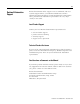
Appendix A Specifications General Specifications 1 Specification 1769-IF4XOF2 Dimensions 118 mm (height) x 87 mm (depth) x 35 mm (width) height including mounting tabs is 138 mm 4.65 in. (height) x 3.43 in (depth) x 1.38 in (width) height including mounting tabs is 5.43 in. Approximate Shipping Weight (with carton) 290g (0.64 lbs.
A-2 Specifications Specification 1769-IF4XOF2 Hazardous Environment Class Class I, Division 2, Hazardous Location, Groups A, B, C, D (UL 1604, C-UL under CSA C22.2 No.
Specifications A-3 Specification 1769-IF4XOF2 Calibration Not required. Accuracy is guaranteed by components. Non-linearity (in percent full scale) ±0.4% Repeatability(5) ±0.4% Input Channel Configuration via wiring of devices, configuration software screen, or the user program (by writing a unique bit pattern into the module’s configuration file). Refer to your controller’s user manual to determine if user program configuration is supported.
A-4 Specifications Specification 1769-IF4XOF2 Max. Capacitive Load (Voltage Outputs) 1 µF Overall Accuracy(2) at 25°C Voltage Terminal: ±0.5% full scale Current Terminal: ±0.5% full scale Overall Accuracy at 0 to 60°C Voltage Terminal: ±0.6% full scale Current Terminal: ±1.0% full scale Accuracy Drift with Temperature Voltage Terminal: ±0.01% full scale per °C Current Terminal: ±0.01% full scale per °C Output Ripple;(3) range 0 - 50 kHz (referred to output range) ±0.
Appendix B Module Addressing and Configuration with MicroLogix 1500 This chapter examines the analog module’s addressing scheme and describes module configuration using RSLogix 500 and MicroLogix 1500. Module Addressing The following memory map shows the input, output, and configuration image tables for the 1769-IF4XOF2. Detailed information for these image tables can be found on page 4-3.
B-2 Module Addressing and Configuration with MicroLogix 1500 1769-IF4XOF2 Input Image The input image file represents input channel data words I/O, channel status bits. Input words 0 through 3 contain the converted analog input data from the field device. Word 4, bits 0 to 3 are the over-range flag bits for input channels 0 to 3. Word 5, bit 0 and 1 are the over-range flag bits for channels 0 and 1. Words 6 and 7, bits 7 through 14 are the data echo.
Module Addressing and Configuration with MicroLogix 1500 B-3 1769-IF4XOF2 Configuration File The configuration file allows you to enable or disable the modules input and/or output channels. It also allows you to select how the Program or Fault mode condition and what the output value will be if the User-defined Safe State is selected. The configuration file is explained in more detail in Configuration Data File on page 4-8.
B-4 Module Addressing and Configuration with MicroLogix 1500 Start RSLogix and create a MicroLogix 1500 application. The following screen appears: While offline, double-click on the IO Configuration icon under the controller folder and the following IO Configuration screen appears. This screen allows you to manually enter expansion modules into expansion slots, or to automatically read the configuration of the controller. To read the existing controller configuration, click on the Read IO Config button.
Module Addressing and Configuration with MicroLogix 1500 B-5 A communications dialog appears, identifying the current communications configuration so that you can verify the target controller. If the communication settings are correct, click on Read IO Config. The actual I/O configuration is displayed. In this example, the 1769-IF4XOF2 is attached to the MicroLogix 1500 processor.
B-6 Module Addressing and Configuration with MicroLogix 1500 Configuring the 1769-IF4XOF2 The 1769-IF4XOF2 analog module is installed in slot 1. To configure the module, double-click on the module/slot. The 1769-IF4XOF2 general configuration screen appears.
Module Addressing and Configuration with MicroLogix 1500 B-7 Analog Input/Output Configuration Each of the four analog input words (channels) and two output words (channels) are disabled by default. To enable a channel, click its Enable box so that a check mark appears in it. For optimum module performance, disable any channel that is not hardwired to a real input.
B-8 Module Addressing and Configuration with MicroLogix 1500 Publication 1769-UM008A-EN-P - November 2001
Appendix C Configuration Using the 1769-IF4XOF2 Combination Analog Module with a CompactLogix System The following is used to generate a Generic or Thin Profile and configure the 1769-IF4XOF2 analog combination module in RSLogix5000. Version 8.02 of RSLogix5000 and the CompactLogix controllers support only the Generic 1769 Module Profile for 1769-IF4XOF2. Version 10 of RSLogix 5000 and the CompactLogix controllers provides a “Thin” Profile for the 1769-IF4XOF2 module.
C-2 Configuration Using the 1769-IF4XOF2 Combination Analog Module with a CompactLogix System Click the File pull down menu and select New or click the New icon. Choose your controller type, name your project, then click OK. A new project screen displays. The area on the left of this screen is called the Controller Organizer. This is where controller properties, tasks, tags and I/O are found. The last entry is called “[0] CompactBus Local”. This is where the local I/O is entered into your project.
Configuration Using the 1769-IF4XOF2 Combination Analog Module with a CompactLogix System C-3 Select either the generic 1769-MODULE or the 1769-IF4XOF2/A and click OK. For RSLogix 5000 version 10, see Thin Profile below. For RSLogix 5000 version 8, see Generic Profile on page C-4. Thin Profile Once you have selected the 1769-IF4XOF2 module and clicked OK, the following screen appears: Enter a name for your module and a description, if desired. You may Click Finish.
C-4 Configuration Using the 1769-IF4XOF2 Combination Analog Module with a CompactLogix System Generic Profile Once you have selected the Generic 1769 Module and clicked OK, the following screen appears: IMPORTANT Do not modify the “Assembly Instance” values. Enter a name and choose “Data-INT” for the “Comm Format”.
Configuration Using the 1769-IF4XOF2 Combination Analog Module with a CompactLogix System Configuring the 1769-IF4XOF2 Analog Combination Module C-5 When you add an I/O module into a CompactLogix system, the Input, Output and Configuration tags are automatically created in the Controller Tag base for that module. TIP When a Thin Profile is used, each of these tags and their sub elements contain descriptive names, which match the documentation for that module.
C-6 Configuration Using the 1769-IF4XOF2 Combination Analog Module with a CompactLogix System One of the following screens displays, depending upon whether you are using a Generic or Thin Profile: RSLogix 5000 Version 8 - Generic Profile RSLogix 5000 Version 10 - Thin Profile Publication 1769-UM008A-EN-P - November 2001
Configuration Using the 1769-IF4XOF2 Combination Analog Module with a CompactLogix System C-7 This Configuration tag is 198 words long. Only the first 6 are needed to configure this module. The remainder of the words in this tag should be a value of 0 decimal.
C-8 Configuration Using the 1769-IF4XOF2 Combination Analog Module with a CompactLogix System You can only modify the configuration file to enable the input and output channels being used. To enable channels: Using RSLogix 5000 version 8 Generic Profile Using RSLogix 5000 version 10 Thin Profile Enter a 1 in bits Local:1:C.Data[0]/4 though Local:1:C.Data[0]/7 for input channels 0 through 3. Set Local:1:C.Ch0InputEn through Local:1:C.Ch3InputEn equal to 1. Enter a 1 in bits Local:1:C.
Configuration Using the 1769-IF4XOF2 Combination Analog Module with a CompactLogix System Accessing the Input and Output Tags C-9 Thin Profile The analog input data file may be accessed by clicking the plus sign to the left of the input tag, Local:1:I. Fault and status information for the module can be found in this input tag. Refer to Chapter 5 concerning the 32-bit Fault value (Local:1:I.Fault). 4, pages 4-3 through 4-6 describe each value in the input file for the 1769-IF4XOF2 module.
C-10 Configuration Using the 1769-IF4XOF2 Combination Analog Module with a CompactLogix System When the Input and Output tags for the 1769-IF4XOF2 module are expanded in the CompactLogix Controller Tags screen, they look like the following: The analog data is presented to the controller in Raw/Proportional format.
Appendix D Two’s Complement Binary Numbers The processor memory stores 16-bit binary numbers. Two’s complement binary is used when performing mathematical calculations internal to the processor. Analog input values from the analog modules are returned to the processor in 16-bit two’s complement binary format. For positive numbers, the binary notation and two’s complement binary notation are identical.
D-2 Two’s Complement Binary Numbers Publication 1769-UM008A-EN-P - November 2001
Glossary The following terms and abbreviations are used throughout this manual. For definitions of terms not listed here refer to Allen-Bradley’s Industrial Automation Glossary, Publication AG-7.1. A/D Converter – Refers to the analog to digital converter inherent to the module. The converter produces a digital value whose magnitude is proportional to the magnitude of an analog input signal.
2 configuration word – Contains the channel configuration information needed by the module to configure and operate each channel. D/A Converter– Refers to the digital to analog converter inherent to the output module. The converter produces an analog dc voltage or current signal whose instantaneous magnitude is proportional to the magnitude of a digital value. dB – (decibel) A logarithmic measure of the ratio of two signal levels.
3 LSB – (Least Significant Bit) The bit that represents the smallest value within a string of bits. For analog combo modules, 8-bit, binary codes are used in the I/O image in the card. For analog combo inputs, the LSB is defined as the bit 7, of the 16-bit field. For analog outputs, the seven rightmost bits are not significant, and the LSB is defined as the eighth bit from the right, bit 7, of the 16-bit field.
4 overall accuracy – The worst-case deviation of the output voltage or current from the ideal over the full output range is the overall accuracy. For inputs, the worst-case deviation of the digital representation of the input signal from the ideal over the full input range is the overall accuracy. this is expressed in percent of full scale. Gain error, offset error, and linearity error all contribute to input and output channel accuracy.
Index A A/D converter 1-6 definition G-1 abbreviations G-1 analog input module definition G-1 overview 1-1 attenuation definition G-1 B before you begin 2-1 bus connector definition G-1 bus interface 1-4 C calibration 1-6, A-3 channel definition G-1 channel diagnostics 5-3 channel reconfiguration time 4-13 channel scan time 4-13 channel status LED 1-5 channel step response 4-12 channel switching time 4-13 channel update time definition G-1 CMRR.
2 Index H heat considerations 3-4 hold last state definition G-2 fault mode 4-10 I inhibit function 5-6 input data formats valid formats/ranges 4-14, 4-15 input filter selection 4-12 input image definition G-2 installation 3-1–3-9 getting started 2-1 grounding 3-10 heat and noise considerations 3-4 L least significant bit. See LSB.
Index T terminal door label 3-18 terminal screw torque 3-16 tools required for installation 2-1 troubleshooting safety considerations 5-1 two’s complement binary numbers D-1 U 3 W wire size 3-16 wiring 3-1 differential inputs 3-18 input module 3-20 mixed transmitter type 3-20 module 3-16 output module 3-21 routing considerations 3-4 update time. See channel update time. update time. See module update time.
4 Index Publication 1769-UM008A-EN-P - November 2001
Publication 1769-UM008A-EN-P - November 2001 4 © 2001 Rockwell International Corporation. Printed in the U.S.A.