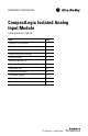
Installation Instructions CompactLogix Isolated Analog Input Module Catalog Number 1769-IF4I Topic Page Important User Information 2 North American Hazardous Location Approval 3 Module Description 5 Prevent Electrostatic Discharge 6 System Assembly 6 Mounting Expansion I/O 7 Replacing a Single Module within a System 9 Replacement Part 10 System Wiring Guidelines 10 I/O Memory Mapping 14 Specifications 18 Additional Resources 23
CompactLogix Isolated Analog Input Module Important User Information Solid-state equipment has operational characteristics differing from those of electromechanical equipment. Safety Guidelines for the Application, Installation and Maintenance of Solid State Controls (Publication SGI-1.1 available from your local Rockwell Automation sales office or online at http://www.rockwellautomation.
CompactLogix Isolated Analog Input Module 3 North American Hazardous Location Approval The following information applies when operating this equipment in hazardous locations. Informations sur l’utilisation de cet équipement en environnements dangereux. Products marked "CL I, DIV 2, GP A, B, C, D" are suitable for use in Class I Division 2 Groups A, B, C, D, Hazardous Locations and nonhazardous locations only.
CompactLogix Isolated Analog Input Module Environment and Enclosure ATTENTION: This equipment is intended for use in a Pollution Degree 2 industrial environment, in overvoltage Category II applications (as defined in IEC 60664-1), at altitudes up to 2000 m (6562 ft) without derating. This equipment is considered Group 1, Class A industrial equipment according to IEC/CISPR 11.
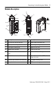
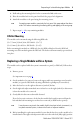
CompactLogix Isolated Analog Input Module 5 Module Description 8a 1 2a 7a 7a 3 OK OK Analog Analog 5a DANGER Do Not Remove RTB Under Power Unless Area is Non-Hazardous 10a Ch0+ N/C Ch0_iRtn N/C Ch1+ 5b 9 Ch0N/C Ch1_iRtn Ch2+ 10 Ch1N/C Ch2_iRtn Ch2- Ch3+ Ch3_iRtn 10b N/C N/C Ch3Ensure Adjacent Bus Lever is Unlatched/Latched Before/After Removing/Inserting Module 4 6 1769-IF4I 2b 7b 7b 8b Item Description Item Description 1 Bus lever (with locking function) 7a Upper tongue-a
CompactLogix Isolated Analog Input Module Prevent Electrostatic Discharge ATTENTION: This equipment is sensitive to electrostatic discharge, which can cause internal damage and affect normal operation. Follow these guidelines when you handle this equipment: • • • • • • Touch a grounded object to discharge potential static. Wear an approved grounding wriststrap. Do not touch connectors or pins on component boards. Do not touch circuit components inside the equipment.
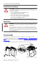
CompactLogix Isolated Analog Input Module 7 1. Disconnect power. 2. Check that the bus lever of the module to be installed is in the unlocked (fully right) position. 3. Use the upper and lower tongue-and-groove slots (1) to secure the modules together (or to a controller). 4. Move the module back along the tongue-and-groove slots until the bus connectors (2) line up with each other. 5. Push the bus lever back slightly to clear the positioning tab (3). Use your fingers or a small screwdriver. 6.
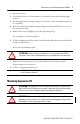
CompactLogix Isolated Analog Input Module Grounding the Module ATTENTION: This product is intended to be mounted to a well-grounded mounting surface such as a metal panel. Additional grounding connections from the power supply's mounting tabs or DIN rail (if used) are not required unless the mounting surface cannot be grounded. Refer to Industrial Automation Wiring and Grounding Guidelines, Rockwell Automation publication 1770-4.1, for additional information.
CompactLogix Isolated Analog Input Module 9 4. Drill and tap the mounting holes for the recommended M4 or #8 screw. 5. Place the modules back on the panel and check for proper hole alignment. 6. Attach the modules to the panel using the mounting screws. TIP If mounting more modules, mount only the last one of this group and put the others aside. This reduces remounting time during drilling and tapping of the next group. 7. Repeat steps 1… 6 for any remaining modules.
CompactLogix Isolated Analog Input Module 7. Slide the replacement module into the open slot. 8. Connect the modules together by locking (fully left) the bus levers on the replacement module and the right-side adjacent module. 9. Replace the mounting screws (or snap the module onto the DIN rail). Replacement Part Terminal block, catalog number 1769-RTBN18 (one per kit). System Wiring Guidelines ATTENTION: Use supply wires suitable for 20 °C (68 °F) above surrounding ambient.
CompactLogix Isolated Analog Input Module 11 • Voltages on Ch+, Ch-, and Ch_iRtn for a single, isolated channel of the 1769-IF4I module must not exceed the maximum overload levels detailed in the Input Specifications on page 21. ATTENTION: To comply with UL restrictions, this equipment must be powered from a source compliant with Class 2 or Limited Voltage/Current. Be careful when stripping wires. Wire fragments that fall into a module could cause damage at power up.
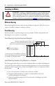
CompactLogix Isolated Analog Input Module Wiring Single-ended Sensor/Transmitter Types + Sensor/ Transmitter Supply Current Transmitter + Signal Voltage Transmitter + Ground Signal Voltage Transmitter + Ground Signal Wiring Mixed Transmitter Types 1769-IF4I Terminal Block Ch0+ Sensor/ + Transmitter Supply - N/C Ch0_iRtn Current Transmitter Signal + N/C Ch0Ch1+ N/C Ch1_iRtn Voltage Transmitter N/C Ch1- + Ground Signal Ch2+ N/C Ch2_iRtn Voltage Transmitter + Ground Signal N/C Ch2C
CompactLogix Isolated Analog Input Module 13 Labeling the Terminals A removable, write-on label is provided with the module. Remove the label from the door, mark the identification of each terminal with permanent ink, and slide the label back into the door. Your markings (ID tag) will be visible when the module door is closed.
CompactLogix Isolated Analog Input Module You can use the bare wire or a spade lug. The terminals will accept a 6.35 mm (0.25 in.) spade lug. The terminal screws are non-captive. Therefore, it is possible to use a ring lug [maximum 1/4 inch o.d. with a 0.139 in. minimum i.d. (M3.5)] with the module. TIP 3. Tighten the terminal screw, making sure the pressure plate secures the wire. Recommended torque when tightening terminal screws is 0.68 N•m (6 lb•in).
CompactLogix Isolated Analog Input Module 15 The bits are defined as follows: • • • • • • SGN = Sign bit in two’s complement format Nu = Not used. Bit set to 0 Sx = General status bit for input channels 0…3 Lx = Low alarm flag bits for input channels 0…3 Hx = High alarm flag bits for input channels 0…3 Ux = Under-range flag bits for channels 0…3 When set, the input signal is under normal range or an open circuit condition exists, in the case of the 4…20 mA range.
CompactLogix Isolated Analog Input Module Configuration Data File The manipulation of the bits from this file is normally done with programming software (for example, RSLogix 5000 or RSNetWorx for DeviceNet software) during initial configuration of the system. In that case, graphical screens are provided by the programmer to simplify configuration. However, some systems, like the 1769-ADN DeviceNet adapter, also allow the bits to be altered as part of the control program, using communication rungs.
CompactLogix Isolated Analog Input Module 17 Configuration Data Array (cont.
CompactLogix Isolated Analog Input Module Bit Definitions for Input Range and Input Data Configuration Define Indicate This These bit settings 15…11 Input Range Select Input Data Select -10…+10V DC 0…5V DC 0…10V DC 4…20 mA 1…5V DC 0…20 mA Raw/Proportional Counts Engineering Units Scaled for PID Percent Range 10 9 8 0 0 0 0 0 0 0 1 1 1 0 1 7…4 3 0 0 0 0 0 0 2 0 0 0 0 1 1 1 0 0 1 1 0 0 0 0 1 0 1 0 1 Specifications Technical Specifications 1769-IF4I Attribute 1769-IF4I Enclosure type
CompactLogix Isolated Analog Input Module 19 Environmental Specifications 1769-IF4I Attribute 1769-IF4I Temperature, operating • IEC 60068-2-1 (Test Ad, Operating Cold) 0…60 °C (32…140 °F) • IEC 60068-2-2 (Test Bd, Operating Dry Heat) • IEC 60068-2-14 (Test Nb, Operating Thermal Shock) Temperature, surrounding air, max 60 °C (140 °F) Temperature, nonoperating • IEC 60068-2-1 (Test Ab, Unpackaged Nonoperating Cold) -40…85 °C (-40…185 °F) • IEC 60068-2-2 (Test Bb, Unpackaged Nonoperating Dry Heat)
CompactLogix Isolated Analog Input Module Environmental Specifications 1769-IF4I Attribute 1769-IF4I Surge transient immunity IEC 61000-4-5 ±1 kV line-earth(CM) on shielded ports Conducted RF immunity IEC 61000-4-6 10V rms with 1 kHz sine-wave 80% AM from 150 kHz…80 MHz Supply power and current ratings Backplane: • 5V DC, 140 mA • 24V DC, 110 mA Voltage Inputs: • ±10V DC • 0…10V DC • 1…5V DC • 0…5V DC (30V DC max) Current Inputs: • 0…20 mA • 4…20 mA Isolation voltage Publication 1769-IN074C-
CompactLogix Isolated Analog Input Module 21 Input Specifications Attribute 1769-IF4I Analog normal operating ranges(1) Voltage: ± 10V DC, 0…10V DC, 0…5V DC, 1…5V DC Current: 0…20 mA, 4…20 mA Full scale analog ranges(1) Voltage: ± 10.5V DC, 0…10.5V DC, 0…5.25V DC, 0.5…5.25V DC Current: 0…21 mA, 3.2…21 mA Number of inputs 4 isolated differential Bus current draw (max) 145 mA at 5V DC 125 mA at 24V DC Heat dissipation 3.
CompactLogix Isolated Analog Input Module Input Specifications (cont.) Attribute Value Accuracy drift with temperature Voltage terminal: ±0.003% per °C Current terminal: ±0.0045% per °C Calibration The module performs only initial factory calibration. Non-linearity (in percent full scale) ±0.03% Repeatability(1) ±0.03% Module error over full temperature range (0…60 °C [+32…140 °F]) Voltage: ±0.3% Current: ±0.
CompactLogix Isolated Analog Input Module 23 Certifications 1769-IF4I Certifications(1) (when product is marked) 1769-IF4I c-UL-us UL Listed for Class I, Division 2 Group A,B,C,D Hazardous Locations, certified for U.S. and Canada. See UL File E10314.
Rockwell Automation Support Rockwell Automation provides technical information on the Web to assist you in using its products. At http://www.rockwellautomation.com/support/, you can find technical manuals, a knowledge base of FAQs, technical and application notes, sample code and links to software service packs, and a MySupport feature that you can customize to make the best use of these tools.