Installation Instructions Compact Combination Fast Analog I/O Module Catalog Number 1769-IF4FXOF2F Topic Page About This Publication 1 Important User Information 2 Electrostatic Discharge 3 Remove Power 3 Hazardous Location 4 Environnements dangereux 4 About the 1769-IF4FXOF2F Module 5 Install the 1769-IF4FXOF2F Module 6 Replacement Parts 11 Field Wiring Connections 11 Specifications 23 Additional Resources 28 About This Publication Use this document as a guide when installing a
Compact Combination Fast Analog I/O Module Important User Information Solid state equipment has operational characteristics differing from those of electromechanical equipment. Safety Guidelines for the Application, Installation and Maintenance of Solid State Controls (Publication SGI-1.1 available from your local Rockwell Automation sales office or online at http://literature.rockwellautomation.
Compact Combination Fast Analog I/O Module 3 Electrostatic Discharge ATTENTION Electrostatic discharge can damage integrated circuits or semiconductors if you touch bus connector pins. Follow these guidelines when you handle the module: • Touch a grounded object to discharge static potential. • Wear an approved wrist-strap grounding device. • Do not touch the bus connector or connector pins. • Do not touch circuit components inside the module. • Use a static-safe work station, if available.
Compact Combination Fast Analog I/O Module Hazardous Location This equipment is suitable for use in Class I, Division 2, Groups A, B, C, D or non-hazardous locations only. The following statement applies to use in hazardous locations. WARNING EXPLOSION HAZARD Substitution of components may impair suitability for Class I, Division 2. Do not replace components or disconnect equipment unless power is switched off or the area is known to be non-hazardous.
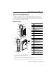
Compact Combination Fast Analog I/O Module 5 About the 1769-IF4FXOF2F Module Compact I/O is suitable for use in an industrial environment when installed in accordance with these instructions. Specifically, this equipment is intended for use in clean, dry environments (Pollution degree 2(1)) and to circuits not exceeding Over Voltage Category II(2) (IEC 60664-1)(3).
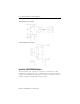
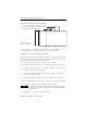
Compact Combination Fast Analog I/O Module Simplified Input Circuit Diagram Simplified Output Circuit Diagram Install the 1769-IF4FXOF2F Module Attach the module to the controller or an adjacent I/O module before or after mounting. For mounting instructions, see Module to Panel Using the Dimensional Template, or Mount Module to a DIN Rail. To work with a system that is already mounted, see Replace a Single Module Within a System.
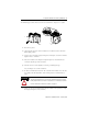
Compact Combination Fast Analog I/O Module 7 The following procedure shows you how to assemble the Compact I/O system. 3 4 2 1 5 1 1. Disconnect power. 2. Check that the bus lever of the module to be installed is in the unlocked (fully right) position. 3. Use the upper and lower tongue-and-groove slots (1) to secure the modules together or to a controller. 4. Move the module back along the tongue-and-groove slots until the bus connectors (2) line up with each other. 5.
Compact Combination Fast Analog I/O Module 8. Lock the end-cap bus terminator (6). IMPORTANT You must use a 1769-ECR or 1769-ECL right or left end cap to terminate the end of the serial communication bus. An I/O configuration fault will occur if an end cap is not used. Replace a Single Module Within a System The module can be replaced while the system is mounted to a panel or DIN rail. 1. Remove power. Refer to Remove Power on page 3. 2.
Compact Combination Fast Analog I/O Module 9 Mount Expansion I/O ATTENTION During panel or DIN rail mounting of all devices, be sure that all debris, that is, metal chips or wire strands, is kept from falling into the module. Debris that falls into the module could cause damage when cycling power. Minimum Spacing Maintain spacing from enclosure walls, wireways, or adjacent equipment. Allow 50 mm (2 in.) of space on all sides for adequate ventilation, as shown.
Compact Combination Fast Analog I/O Module Module to Panel Using the Dimensional Template Spacing for single-wide modules 35 mm (1.378 in.) Spacing for one-and-a-half wide modules 52.5 mm (2.067 in.) Refer to host controller documentation for this NOTE: Overall spacing tolerance ±0.44 mm (0.016 in.) Locate holes every 17.5 mm (0.689 in.) to allow for a mix of single-wide and one-and-a-half-wide modules (for example, the 1769-OA16 module).
Compact Combination Fast Analog I/O Module 11 Mount Module to a DIN Rail The module can be mounted using these DIN rails: • 35 x 7.5 mm (EN 50 022 - 35 x 7.5) • 35 x 15 mm (EN 50 022 - 35 x 15) To mount the module on a DIN rail follow these steps. 1. Close the DIN rail latches. 2. Press the DIN rail mounting area of the module against the DIN rail. The latches will momentarily open and lock into place.
Compact Combination Fast Analog I/O Module System Wiring Guidelines Consider the following when wiring your system: • All module commons (ANLG COM) are connected in the analog module. • The analog common (ANLG COM) is not connected to earth ground inside the module. • Channels are not isolated from each other. • Use Belden 8761, or equivalent, shielded wire.
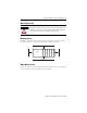
Compact Combination Fast Analog I/O Module 13 Wire Differential Inputs Belden 8761 Cable (or equivalent) + V in 0+ V in 1+ V/I in 0V/I in 1 - – I in 1+ I in 0+ V in 3+ Earth Ground the V in 2 + Shield Locally at the V/I in 2Module V/I in 3 - Differential Voltage Transmitter(1) I in 2+ I in 3+ ANLG Com ANLG Com V out 0+ V out 1+ I out 0+ I out 1+ Differential Current Transmitter(1) + – Earth Ground the Shield Locally at the Module (1) The sensor power supply must be rated Class 2.
Compact Combination Fast Analog I/O Module Wire Mixed-input Transmitter Types Signal Single-ended Voltage Transmitter V in 0+ I in 0+ + – V/I in 0 V in 1+ I in 1+ + Differential Voltage Transmitter – Supply Signal – + + Differential Current Transmitter – Supply Signal – V/I in 1V in 2+ I in 2+ V/I in 2V in 3+ I in 3+ V/I in 3ANLG Com ANLG Com V out 0+ + 2-wire Current Transmitter 1769-IF4FXOF2F Terminal Block Signal + Sensor/ Transmitter Power Supply(1) I out 0+ V out 1+ I out 1 +
Compact Combination Fast Analog I/O Module 15 Wire Analog Outputs 1769-IF4FXOF2F Terminal Block V in 0+ I in 0+ V/I in 0 V in 1+ I in 1+ V/I in 1V in 2+ I in 2+ V/I in 2V in 3+ I in 3+ Voltage Load V/I in 3- Earth Ground ANLG Com ANLG Com V out 0+ I out 0+ V out 1+ Current Load I out 1 + Earth Ground ATTENTION Analog outputs may fluctuate for less than a second when power is applied or removed. This characteristic is common to most analog outputs.
Compact Combination Fast Analog I/O Module To remove the terminal block, loosen the upper and lower retaining screws. The terminal block will back away from the module as you remove the screws. When replacing the terminal block, torque the retaining screws to 0.46 Nm (4.1 in-lbs). Upper Retaining Screw Wiring the Finger-safe Terminal Block Lower Retaining Screw Wire the Finger-safe Terminal Block When wiring the terminal block, keep the finger-safe cover in place. 1.
Compact Combination Fast Analog I/O Module 17 Wire Size and Terminal Screw Torque Each terminal accepts two wires with the following restrictions:. Wire Type Wire Size Terminal Screw Torque Retaining Screw Torque Solid Cu-90°C (194°F) #14…#22 AWG 0.68 Nm (6 in-lbs) 0.46 Nm (4.1 in-lbs) Stranded Cu-90°C (194°F) #16…#22 AWG 0.68 Nm (6 in-lbs) 0.46 Nm (4.1 in-lbs) Configure the 1769-IF4FXOF2F Module The following I/O memory mapping lets you configure the 1769-IF4FXOF2F module.
Compact Combination Fast Analog I/O Module Input Data File For each module, slot x, words 0…3 in the input data file contain the converted value of the module’s analog input channels. Word 4 in the input data file contains the time stamp value corresponding to the module's last input data sampling period. Words 5 and 6 in the input data file contain status bits for the analog input channels. Word 7 in the input data file contains status bits for the analog output channels.
Compact Combination Fast Analog I/O Module 19 Configuration Data File The manipulation of bits from this file is normally done with programming software (for example, RSLogix 500 software or RSNetWorx for DeviceNet software) during initial configuration of the system. In that case, graphical screens provided by the programming software simplify configuration.
Compact Combination Fast Analog I/O Module Word 22 SGN Process Alarm High Data Value Channel 3 0 Word 23 SGN Process Alarm Low Data Value Channel 3 0 Word 24 SGN Alarm Dead Band Value Channel 3 0 Word 25 Word 26 Reserved EC Word 27 Reserved Reserved EHI Outpt Fm ChI0 ELI LC ER Reserved FM PM 0 PFE Outpt Tp/Rnge Sel ChI0 Word 28 SGN Fault Value Channel 0 0 0 Word 29 SGN Program (Idle) Value Channel 0 0 0 Word 30 SGN Clamp High Data Value Channel 0 0 0 Word 31 S
Compact Combination Fast Analog I/O Module 21 • Process Alarm High Data Value Channel x = Provides the ability to configure the Input Process Alarm High Value. • Process Alarm Low Data Value Channel x = Provides the ability to configure the Input Process Alarm Low Value. • Alarm Dead Band Value Channel x = Provides the ability to configure the Input Process Dead Band Value. • Reserved = Bits not used, must be set to 0. • EHI = Enable Output Channel Interrupt on High Clamp Alarm.
Compact Combination Fast Analog I/O Module Define To Select Make these bit settings 15 Input Type / Range Select Input Data Format Select 14 13 12 11 10 09 08 03 02 01 00 -10 to +10V dc 0 0 0 0 0 to 5V dc 0 0 0 1 0 to 10V dc 0 0 1 0 4 to 20 mA 0 0 1 1 1 to 5V dc 0 1 0 0 0 to 20 mA 0 1 0 1 Raw/ Proportional Counts 0 0 0 Engineering Units 0 0 1 Scaled for PID 0 1 0 Percent Range 0 1 1 07 06 05 04 Define To Select Make these bit settings
Compact Combination Fast Analog I/O Module 23 Specifications Compact Combination Fast Analog I/O Module - 1769-IF4FXOF2F Attribute Value Dimensions (HxWxD), Approx. 118 mm (height) x 87 mm (depth) x 35 mm (width) Height including mounting tabs is 138 mm (5.43 in.) 4.65 in. (height) x 3.43 in (depth) x 1.38 in (width) Height including mounting tabs is 138 mm (5.43 in.) Approximate Shipping Weight (with carton) 290 g (0.64 lbs.
Compact Combination Fast Analog I/O Module Certifications Certification Value • C-UL certified (under CSA C22.2 No. 142) Agency Certification • UL 508 listed • CE compliant for all applicable directives Hazardous Environment Class Class I, Division 2, Hazardous Location, Groups A, B, C, D (UL 1604, C-UL under CSA C22.2 No.
Compact Combination Fast Analog I/O Module Attribute Value Accuracy Drift with Temperature Current load: ±0.0058% FS per °C Voltage load: +/-0.0086% FS per °C Output Ripple(1) range 0 to 50 kHz (referred to output range) ±0.05% Non-linearity (in percent full scale) ±0.05% Repeatability(2) (in percent full scale) ±0.05% Output Error Over Full Temperature Range (0 to 60°C [+32 to +140°F]) Current: +/-0.4% of full scale Voltage: +/-0.
Compact Combination Fast Analog I/O Module Input Specifications Attribute Value Analog Normal Operating Voltage: ± 10V dc, 0 to 10V dc, 0 to 5V dc, 1 to 5V dc Current: 0 to 20 mA, 4 to 20 mA Ranges(1) Full Scale Analog Ranges(1) Voltage: ± 10.5V dc, -0.5 to 10.5V dc, -0.5 to 5.25V dc, 0.5 to 5.25V dc Current: 0 to 21 mA, 3.2 to 21 mA Number of Inputs Four differential or single-ended Converter Type Successive Approximation Response Speed per Channel Input filter and configuration dependent.
Compact Combination Fast Analog I/O Module Attribute 27 Value Accuracy Drift with Temperature Voltage Terminal: ±0.003% per °C Current Terminal: ±0.0045% per °C Calibration None required Non-linearity (in percent full scale) ±0.03% Repeatability(1) ±0.03% Module Error over Full Voltage: 0.2% Temperature Range (0 to +60 °C [+32 °F to +140 °F]) Current: 0.3% Channel Diagnostics Over- or under-range by bit reporting, process alarms Maximum Overload at Input Voltage Terminal: ±30V dc continuous, 0.
Additional Resources For more information refer to the following publications. Resource Description 1768 CompactLogix Controllers User Manual, publication number 1768-UM001 Detailed description of how to install and use your 1768 CompactLogix controller.