Compact I/O Combination Fast Analog I/O Module User Manual (Catalog Number 1769-IF4FXOF2F)
Important User Information Solid state equipment has operational characteristics differing from those of electromechanical equipment. Safety Guidelines for the Application, Installation and Maintenance of Solid State Controls (publication SGI-1.1 available from your local Rockwell Automation sales office or online at http://literature.rockwellautomation.com) describes some important differences between solid state equipment and hard-wired electromechanical devices.
Table of Contents Preface Introduction . . . . . . . . . . . . . . . . About This Publication . . . . . . . . Who Should Use This Publication Additional Resources. . . . . . . . . . . . . . . . . . . . . . . . . . . . . . . . . . . . . . . . . . . . . . . . . . . . . . . . . . . . . . . . . . . . . . . . . . . . . . . . . . . . . . . . . . . . . . 7 7 7 8 . . . . . . . . . . . . . . . . . . . . . . . . . . . . . . . . . . . . . . . . . . . . . . . . . . . . . . . . . . .
Table of Contents Input Data File . . . . . . . . . . . . . . . . . . . . . . . . . . . . . . . . Time Stamp Value (Word 4) . . . . . . . . . . . . . . . . . . . . General Input Status Bits (SI0…SI3) . . . . . . . . . . . . . . Low Alarm Flag Bits (LI0 …LI3) . . . . . . . . . . . . . . . . . High Alarm Flag Bits (HI0…HI3) . . . . . . . . . . . . . . . . Over-range Flag Bits (OI0…OI3) . . . . . . . . . . . . . . . . Under-range Flag Bits (UI0…UI13) . . . . . . . . . . . . . . .
Table of Contents Power Cycle Diagnostics . . . . . . . . . . . . . Channel Diagnostics . . . . . . . . . . . . . . . . Out-of-range Detection . . . . . . . . . . . Process Alarm Detection . . . . . . . . . . Output Clamp Detection . . . . . . . . . . Non-critical Versus Critical Module Errors. Module Error Definition Table . . . . . . . . . Module Error Field. . . . . . . . . . . . . . . Extended Error Information Field . . . . Error Codes . . . . . . . . . . . . . . . . . . . . . .
Table of Contents Appendix C Configuration Using the RSLogix 5000 Generic Profile for CompactLogix Controllers Introduction . . . . . . . . . . . . . . . . . . . . . . . . . . . . . . . . . . . . 79 Add the Module to Your Project . . . . . . . . . . . . . . . . . . . . . 79 Configure Each I/O Module. . . . . . . . . . . . . . . . . . . . . . . . . 82 Appendix D Two’s Complement Binary Numbers Positive Decimal Values . . . . . . . . . . . . . . . . . . . . . . . . . . . 83 Negative Decimal Values . . . .
Preface Introduction Read this preface to familiarize yourself with the rest of the manual. Topic About This Publication Page About This Publication 7 Who Should Use This Publication 7 Additional Resources 8 This manual is a guide for using the Compact I/O Combination Fast Analog I/O Module, catalog number 1769-IF4FXOF2F. It describes the procedures you use to configure, operate, and troubleshoot your module.
Preface Additional Resources These documents contain additional information about control systems that use Compact I/O modules. Resource Description MicroLogix 1500 User Manual, publication 1764-UM001 A user manual containing information on how to install, use, and program your MicroLogix 1500 controller. DeviceNet Adapter User Manual, publication 1769-UM001 A user manual containing information on how to install and use your 1769-ADN DeviceNet adapter.
Chapter 1 Overview Introduction Topic Module Description Page Module Description 9 System Overview 11 Module Operation 11 The module converts and digitally stores analog data for retrieval by controllers, such as the CompactLogix or MicroLogix 1500 controllers. The module also converts digital data from controllers to provide analog output data. The module provides the following input and output types and ranges.
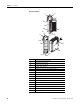
Chapter 1 Overview Hardware Features 2a 1 3 OK Analog DANGER Do Not Remove RTB Under Power Unless Area is Non-Hazardous 10a V in 0 + V in 1+ V/I in 1I in 1+ V/I in 0I in 0 + V in 2+ V in 3+ 10 V/I in 2 V/I in 3I in 2+ I in 3 + ANLG Com ANLG Com V out 0+ 10b V out 1+ I out 0+ I out 1+ Ensure Adjacent Bus Lever is Unlatched/Latched Before/After Removing/Inserting Module 4 1769-IF4FXOF2F 8a 7a 7a 2b OK Analog 5a 5b 9 6 7b 10 8b 7b Item Description 1 Bus lever (with locking fun
Overview System Overview Chapter 1 The module communicates to the controller through the bus interface. The module also receives 5 and 24V DC power through the bus interface. You can install as many analog modules as your power supply can support. However, the modules may not be located more than eight modules away from the system power supply.
Chapter 1 Overview Each time a new output value is sent to the module, it is tested for an over-range or under-range condition. In addition, the module supports user-configured high and low output clamps for each output channel. If any of these conditions are detected, unique bits are set in the output-channel status word. The channel status words are described in the Input Data File on page 36. The controller uses two’s complement binary data when communicating with the module.
Chapter 2 Installation and Wiring Introduction Topic General Considerations Page General Considerations 13 Assemble the Compact I/O System 16 Mounting the Module 17 Replace a Single Module Within a System 19 Grounding the Module 20 System Wiring Guidelines 21 Label the Terminals 24 Remove the Finger-safe Terminal Block 25 Wire the Finger-safe Terminal Block 25 Wire the Modules 27 The Compact I/O system is suitable for use in an industrial environment when installed in accordance wi
Chapter 2 Installation and Wiring Hazardous Location Considerations This equipment is suitable for use in Class I, Division 2, Groups A, B, C, D or nonhazardous locations only. The following attention statement applies to use in hazardous locations. ATTENTION EXPLOSION HAZARD • Substitution of components may impair suitability for Class I, Division 2. • Do not replace components or disconnect equipment unless power has been switched off or the area is known to be nonhazardous.
Installation and Wiring Chapter 2 Remove Power ATTENTION Remove power before removing or inserting this module. When you remove or insert a module with power applied, an electrical arc may occur. An electrical arc can cause personal injury or property damage by: • sending an erroneous signal to your system’s field devices, causing unintended machine motion. • causing an explosion in a hazardous environment.
Chapter 2 Installation and Wiring Assemble the Compact I/O System The module can be attached to the controller or an adjacent I/O module before or after mounting. For mounting instructions, see Panel Mounting By Using the Dimensional Template on page 18, or Mount to a DIN Rail on page 19. To work with a system that is already mounted, see Replace a Single Module Within a System on page 19. 3 4 2 1 6 1 5 1. Disconnect power. 2.
Installation and Wiring Chapter 2 6. To allow communication between the controller and module, move the bus lever fully to the left (4) until it clicks. Make sure it is locked firmly in place. ATTENTION When attaching I/O modules, it is very important that the bus connectors are securely locked together to be sure of proper electrical connection. 7. Attach an end cap terminator (5) to the last module in the system by using the tongue-and-groove slots as before. 8. Lock the end cap bus terminator (6).
Chapter 2 Installation and Wiring Mount to a Panel Mount the module to a panel by using two screws per module. Use M4 or #8 panhead screws. Mounting screws are required on every module. Panel Mounting By Using the Dimensional Template Locate holes every 17.5 mm (0.689 in.) to allow for a mix of single-wide and one-and-a-half-wide modules (for example, the 1769-OA16 module). Overall hole spacing tolerance: ±0.4 mm (0.016 in.). Host Controller Spacing for single-wide modules 35 mm (1.378 in.).
Installation and Wiring Chapter 2 6. Attach the modules to the panel by using the mounting screws. TIP If mounting more modules, mount only the last one of this group and put the others aside. This reduces remounting time during drilling and tapping of the next group. 7. Repeat steps 1…6 for any remaining modules. Mount to a DIN Rail The module can be mounted by using the following DIN rails: • 35 x 7.5 mm (EN 50 022 - 35 x 7.5) • 35 x 15 mm (EN 50 022 - 35 x 15).
Chapter 2 Installation and Wiring 4. On the right-side adjacent module, move its bus lever to the right (unlock) to disconnect it from the module to be removed. 5. Gently slide the disconnected module forward. If you feel excessive resistance, check that the module has been disconnected from the bus, and that both mounting screws have been removed or DIN latches opened.
Installation and Wiring System Wiring Guidelines Chapter 2 Consider the following when wiring your system: • All module commons (ANLG Com) are connected in the analog module. • The analog common (ANLG Com) is not connected to earth ground inside the module. • Channels are not isolated from each other. • For optimum accuracy, limit overall cable impedance by keeping your cable as short as possible. Locate the I/O system as close to your sensors or actuators as your application will permit.
Chapter 2 Installation and Wiring Effect of Transducer/Sensor and Cable Length Impedance on Voltage Input and Output Accuracy For voltage inputs and outputs, the length of the cable used between the transducer/sensor/load and the module can affect the accuracy of the data provided by the module.
Installation and Wiring Chapter 2 As input source impedance (Rs) and/or resistance (DC) of the cable (Rc) get larger, system accuracy decreases. If you determine that the inaccuracy error is significant, implementing the following equation in the control program can compensate for the added inaccuracy error due to the impedance of the source and cable.
Chapter 2 Installation and Wiring For example, for Belden 8761 two conductor, shielded cable and a 1769-IF4 input module: Rc = 52.5 Ω/1000 m Rs = 1 Ω Ri = 220 KΩ Vin % Ai = ⎛ 1 – ---------⎞ × 100 ⎝ Vs ⎠ Effect of Output Impedance and Cable Length on Accuracy Length of Cable DC Resistance of the Cable Rc Accuracy Impact at the Input Module 50 m (164 ft) 2.625 Ω 0.00284% 100 m (328 ft) 5.25 Ω 0.00523% 200 m (656 ft) 10.50 Ω 0.01% 300 m (984 ft) 15.75 Ω 0.
Installation and Wiring Remove the Finger-safe Terminal Block Chapter 2 When wiring field devices to the module, it is not necessary to remove the terminal block. If you remove the terminal block, use the write-on label on the side of the terminal block to identify the module slot location and type. RTB position (for one-and-a-half size modules) can be indicated by circling either the R for right side or L for left side.
Chapter 2 Installation and Wiring 3. Route the wire under the terminal pressure plate. You can use the bare wire or a spade lug. The terminals accept a 6.35 mm (0.25 in.) spade lug. TIP The terminal screws are non-captive. Therefore, it is possible to use a ring lug (maximum 1/4 in. o.d. with a 0.139 in. minimum i.d. (M3.5)) with the module. 4. Tighten the terminal screw making sure the pressure plate secures the wire. Recommended torque when tightening terminal screws is 0.68 N•m (6 lb•in).
Installation and Wiring Chapter 2 Wire the Modules ATTENTION To prevent shock hazard, care should be taken when wiring the module to analog signal sources. Before wiring any analog module, disconnect power from the system power supply and from any other source to the analog module. After the analog module is properly installed, follow the wiring procedure below. For proper operation and high immunity to electrical noise, always use Belden 8761 (shielded, twisted-pair) or equivalent wire.
Chapter 2 Installation and Wiring 4. At one end of the cable, twist the drain wire and foil shield together. Under normal conditions, this drain wire and shield junction must be connected to earth ground, via a panel or DIN rail mounting screw at the analog I/O module end. Keep the length of the drain wire as short as possible. In environments where high frequency noise may be present, it may be necessary to also ground the cable shields to earth via a 0.1 µF capacitor at the sensor end. 5.
Installation and Wiring Chapter 2 Wire Differential Inputs Belden 8761 Cable (or equivalent) V in 1+ + V in 0+ V/I in 0- V/I in 1 I in 1+ V in 3+ V/I in 3 - V in 2 + V/I in 2I in 2+ I in 3+ ANLG Com V out 1+ I out 1+ Differential Current Transmitter (1) – I in 0+ Differential Voltage Transmitter (1) Earth Ground the Shield Locally at the Module ANLG Com V out 0+ I out 0+ + – (1) The sensor power supply must be rated Class 2.
Chapter 2 Installation and Wiring Wiring Mixed-input Transmitter Types Single-ended Voltage Transmitter Signal V in 0+ I in 0+ + – + Differential Signal Voltage – Transmitter – Supply + + Differential Signal Current – Transmitter – Supply + Two-wire Current Transmitter Terminal Block Signal + V/I in 0 V in 1+ I in 1+ V/I in 1V in 2+ I in 2+ V/I in 2V in 3+ I in 3+ V/I in 3ANLG Com ANLG Com V out 0+ I out 0+ V out 1+ I out 1 + Sensor/ + Transmitter (1) Power Supply – (1) The sensor power suppl
Installation and Wiring Chapter 2 Wiring Analog Outputs Terminal Block V in 0+ I in 0+ V/I in 0 V in 1+ I in 1+ V/I in 1V in 2+ I in 2+ V/I in 2V in 3+ I in 3+ Voltage Load V/I in 3- Earth Ground ANLG Com ANLG Com V out 0+ I out 0+ V out 1+ Current Load I out 1 + Earth Ground ATTENTION Publication 1769-UM019A-EN-P - October 2008 Analog outputs may fluctuate for less than a second when power is applied or removed. This characteristic is common to most analog outputs.
Chapter 2 Installation and Wiring Notes: 32 Publication 1769-UM019A-EN-P - October 2008
Chapter 3 Module Data, Status, and Channel Configuration Introduction Topic 33Publication 1769-UM019A-EN-P - October 2008 Page Module Addressing 34 Input Data File 36 Output Data File 39 Configuration Data File 40 Input Channel Configuration 41 Output Channel Configuration 49 33
Chapter 3 Module Data, Status, and Channel Configuration Module Addressing This memory map shows the output, input, and configuration tables for the module.
Module Data, Status, and Channel Configuration Chapter 3 Word 7 holds the general status bits for each output channel as well as the over and under output-clamp status bits. To receive valid status information, the output channel must be enabled. Words 8 and 9 contain the data echo values for the most recent data sent to the output channels. Output Image Output words 0 and 1 contain the digital data to be converted by outputs 0 and 1 into analog output signals.
Chapter 3 Module Data, Status, and Channel Configuration Input Data File The input data table lets you access analog input-module read data for use in the control program, via word and bit access. The data table structure is shown in the table below. For each input module, slot x, words 0…3 in the input data file contain the converted values of the analog inputs. The most significant bit (MSB) is the sign bit, which is in two’s complement format. ‘Nu’ indicates not used with the bit set to zero.
Module Data, Status, and Channel Configuration Chapter 3 Low Alarm Flag Bits (LI0 …LI3) Word 6, bits 3, 7, 11, and 15 contain the low alarm flag bits for input channels 0…3. If set (1), these bits indicate the input signal is outside the user-defined range. The module continues to convert analog data to minimum full-range values. The bit is automatically reset (0) when the low alarm condition clears, unless the channel’s alarm bits are latched.
Chapter 3 Module Data, Status, and Channel Configuration General Output Status Bits (SO0 and SO1) Word 7, bits 0 and 1 contain the general operational status bits for output channels 0 and 1. When set (1), these bits indicate an output-clamp range error associated with that channel. The over- and under-range bits are logically ORed to the appropriate general status bit.
Module Data, Status, and Channel Configuration Output Data File Word/ Bit 15 14 Chapter 3 The output data table lets you write analog output data and unlatch command data to the module with the control program and bit access. The data table structure is shown in the table below. For each module, slot x, words 0 and 1 in the output data file contain the digital values of the data to be converted to analog signals by the module outputs.
Chapter 3 Module Data, Status, and Channel Configuration Configuration Data File The configuration file lets you determine how each individual input channel will operate. Parameters such as the input type and data format are set up by using this file. This data file is writable and readable. The default value of the configuration data table is all zeros.
Module Data, Status, and Channel Configuration Chapter 3 Configuration Data File Word/Bit 15 14 13 12 11 10 09 08 Word 26 EC Reserved Word 27 Reserved Word 28 SGN Fault Value Channel 0 0 0 Word 29 SGN Program (Idle) Value Channel 0 0 0 Word 30 SGN Clamp High Data Value Channel 0 0 0 Word 31 SGN Clamp Low Data Value Channel 0 0 0 Word 32 SGN Ramp Rate Channel 0 0 0 0 PFE Output Data Format Ch0 Word 33 07 06 05 04 03 02 01 00 EHI ELI LC ER FM PM 0 PF
Chapter 3 Module Data, Status, and Channel Configuration Bit Definitions for Input Channel Configuration Words Define To choose Make these bit settings 15 Input Filter Selection/ -3 dB Frequency Enable Interrupt (EI) (1) (2) 14 13 12 11 10 09 03 02 01 00 60 Hz 0 0 0 0 50 Hz 0 0 0 1 5 Hz 0 0 1 0 10 Hz 0 0 1 1 100 Hz 0 1 0 0 250 Hz 0 1 0 0 500 Hz 0 1 1 0 1000 Hz 0 1 1 1 No Filter 1 0 0 0 Enable 07 06 05 04 1 Disable 0 Process Alarm Latch (
Module Data, Status, and Channel Configuration Chapter 3 Enable/Disable Channel (EC) This configuration selection lets each channel be enabled individually. TIP When a channel is not enabled (EC = 0), no voltage or current reading is provided to the controller by the A/D converter. Any analog input channel that is not wired to a voltage or current source should not be enabled in the module configuration file.
Chapter 3 Module Data, Status, and Channel Configuration Channel Step Response The selected channel filter frequency determines the channel’s step response. The step response is the time required for the analog input signal to reach 100% of its expected final value. This means that if an input signal changes faster than the channel step response, a portion of that signal will be attenuated by the channel filter.
Module Data, Status, and Channel Configuration Chapter 3 Input Type/Range Selection This selection lets you configure each input channel individually and provides the ability to read the configured range selections. Input Data Selection Formats This selection configures each input channel to present analog data in any of the following formats: • • • • Raw/Proportional Data Engineering Units Scaled-for-PID Percent Range See Valid Input Data on page 46.
Chapter 3 Module Data, Status, and Channel Configuration Percent Range The input data is presented as a percentage of the normal operating range. For example, 0…10V DC equals 0…100%. The amount over and under the normal operating range (the full-scale range) is also supported. Valid Input Data Word Formats/Ranges This table shows the valid formats and minimum/maximum data ranges provided by the module. Valid Input Data Normal Operating Input Range Full Range(1) -10…10V DC -10.5…10.
Module Data, Status, and Channel Configuration Chapter 3 If you enter a zero for the Real Time Sample Rate, the module initiates conversion cycles at the fastest rate possible, controlled by the filter setting selected for each enabled channel. Once all of the channels’ input data have been converted, the Input Data file is updated for all enabled channels at the same time.
Chapter 3 Module Data, Status, and Channel Configuration Process Alarms Process alarms alert you when the module has exceeded configured high or low limits for each input channel. You can latch process alarms. Process alarms can generate interrupts.(1) A channel’s process alarms are set at two user-configurable alarm trigger points. • Process Alarm High • Process Alarm Low The operation of each input channel’s process alarms are controlled by bits in the Configuration Data file.
Module Data, Status, and Channel Configuration Chapter 3 Alarm Deadbands High alarm turns OFF. High alarm turns ON. High Normal Input Range Alarm Deadbands Low Low alarm turns OFF. Low alarm turns ON. The module checks for an alarm deadband value that is less than 0 or large enough to be equal to or exceed one-half of the difference between the high alarm and low alarm values. When one of these conditions occurs, a module configuration fault results.
Chapter 3 Module Data, Status, and Channel Configuration Bit Definitions for Output Range and Output Data Configuration Words Define To choose Make these bit settings 15 Output Type/Range Select 14 13 12 11 10 09 08 03 02 01 00 -10…10V DC 0 0 0 0 0…5V DC 0 0 0 1 0…10V DC 0 0 1 0 4…20 mA 0 0 1 1 1…5V DC 0 1 0 0 0…20 mA 0 1 0 1 Output Data Raw/Proportional Format Select Counts 0 0 0 Engineering Units 0 0 1 Scaled for PID 0 1 0 Percent Range 0 1 1
Module Data, Status, and Channel Configuration Chapter 3 Program Value Use each output channel’s program value word to set the analog values for the outputs to assume when the system enters the Program mode. Valid values are dependent upon the type/range and data format selected for each output channel or the user-defined output clamp values.
Chapter 3 Module Data, Status, and Channel Configuration Fault Value Use each output channel’s fault value word to set the analog values for the outputs to assume when the system enters the Fault mode. Valid values depend upon the type/range and data format selected for each output channel or the user-defined output clamp values.
Module Data, Status, and Channel Configuration Chapter 3 Clamp High and Clamp Low Data Values Clamping is disabled on a per channel basis for each output channel by entering a 0 value in both the clamp high data value and clamp low data value words in the configuration-data file. If either the clamp high data value or clamp low data value words have a non-zero value entered, clamping is enabled for the corresponding output channel.
Chapter 3 Module Data, Status, and Channel Configuration Enable Ramping (ER) If the selection is enabled (ER = 1), the module controls the ramp rate of the output when the system transitions from Run to Fault mode based on the value entered in the channel’s ramp-rate configuration word. If the selection is disabled (ER = 0), no ramping control of the output is provided. The default setting is disabled. TIP N Not all controllers support alternate output states and this function.
Module Data, Status, and Channel Configuration Chapter 3 Ramp Rates for Output Type/Range and Data Formats Output Data Format Percent of Full Scale Output Type/Range Total Counts in Full Scale Number of Counts for Every 1% of Ramp Rate Real Units/Second for Every 1% of Ramp Rate -10…10V DC 21,000 208 0.20V/s 0…5V DC 11,500 112 0.05V/s 0…10V DC 11,000 108 0.10V/s 1…5V DC 11,872 116 0.04V/s 0…20 mA 10,500 104 0.20 mA/s 4…20 mA 11,124 108 0.
Chapter 3 Module Data, Status, and Channel Configuration Output Data Selection Formats This selection configures each output channel to accept digital data in any of the following formats: • • • • Raw/Proportional Data Engineering Units Scaled-for-PID Percent Range See Valid Output Data on page 57. Raw/Proportional Data The value sent by the controller to the output channel is proportional to the selected output and scaled into the maximum data range allowed by the bit resolution of the D/A converter.
Module Data, Status, and Channel Configuration Chapter 3 Valid Output Data Word Formats/Ranges This table shows the valid formats and minimum/maximum data ranges provided by the module. Valid Output Data Normal Operating Output Range Full Range(1) -10…10V DC -10.5…10.5V 0…5V DC -0.5…5.
Chapter 3 Module Data, Status, and Channel Configuration Notes: 58 Publication 1769-UM019A-EN-P - October 2008
Chapter 4 Module Diagnostics and Troubleshooting Introduction Topic Safety Considerations Page Safety Considerations 59 Power Cycle Diagnostics 60 Channel Diagnostics 61 Non-critical Versus Critical Module Errors 61 Module Error Definition Table 62 Error Codes 63 Module Inhibit Function 67 Contacting Rockwell Automation 68 Safety considerations are an important element of proper troubleshooting procedures.
Chapter 4 Module Diagnostics and Troubleshooting Stand Clear of the Machine When troubleshooting any system problem, have all personnel remain clear of the machine. The problem could be intermittent, and sudden unexpected machine motion could occur. Have someone ready to operate an emergency stop switch in case it becomes necessary to shut off power to the machine.
Module Diagnostics and Troubleshooting Channel Diagnostics Chapter 4 When any channel is enabled, the module performs a diagnostic check to see that the channel has been properly configured. In addition, the module checks each channel during every conversion cycle for input channel over-range and under-range, input channel high and low process alarm conditions, and output channel high and low clamp conditions.
Chapter 4 Module Diagnostics and Troubleshooting Module Error Definition Table Module errors are expressed in two fields as four-digit Hex format with the most significant digit as don’t care and irrelevant. The two fields are Module Error and Extended Error Information.
Module Diagnostics and Troubleshooting Error Codes Chapter 4 Error codes can help troubleshoot your module.
Chapter 4 Module Diagnostics and Troubleshooting Extended Error Codes for Configuration Errors Module Error Code Extended Error Information Code Binary Binary X40D 010 0 0000 1101 Invalid alarm data (channel 0) X40E 010 0 0000 1110 Invalid alarm data (channel 1) X40F 010 0 0000 1111 Invalid alarm data (channel 2) X410 010 0 0001 0000 Invalid alarm data (channel 3) X411 010 0 0001 0001 Invalid input filter selected (channel 0) X412 010 0 0001 0010 Invalid input filter selected (c
Module Diagnostics and Troubleshooting Chapter 4 Invalid Input Format Selected These error codes occur when the 3-bit input format code for the indicated channel is not one of the assigned input format codes for the module. See Bit Definitions for Input Range and Input Data Configuration Words on page 42 for details on the assigned input format codes for the module.
Chapter 4 Module Diagnostics and Troubleshooting Invalid Output Range Selected These error codes occur when the 4-bit output range code for the indicated channel is not one of the assigned output range codes for the module. See Bit Definitions for Output Range and Output Data Configuration Words on page 50 for details on the assigned output range codes for the module.
Module Diagnostics and Troubleshooting Chapter 4 Invalid Clamp Value Selected These error codes occur when the value entered is not within the full-range limits of the indicated channel, as determined by the channel’s output range/type and format setting, or if the low clamp value is greater than the high clamp value.
Chapter 4 Module Diagnostics and Troubleshooting Contacting Rockwell Automation If you need to contact Rockwell Automation for assistance, please have the following information available: • A clear statement of the problem, including a description of what the system is actually doing. Note the state of the status indicators; also note input and output image words for the module. • List of remedies you have already tried • Controller type and firmware number (See the label on the controller.
Appendix A Specifications Introduction Topic Page General Specifications 69 Input Specifications 70 Output Specifications 71 Certifications 72 Replacement Parts 72 General Specifications Attribute Value Dimensions (HxWxD), approx. 118 x 87 x 35 mm (4.65 x 3.43 x 1.38 in.) Height including mounting tabs is 138 mm (5.43 in.) Shipping weight, approx. (with carton) 290 g (0.
Appendix A Specifications Input Specifications Attribute Value Analog normal operating ranges(1) ±10V DC 0…10V DC 0…5V DC 1…5V DC 0…20 mA 4…20 mA Full scale analog ranges(1) ±10.5V DC -0.5…10.5V DC -0.5…5.25V DC 0.5…5.25V DC 0…21 mA 3.
Specifications Appendix A Output Specifications Attribute Value ±10V DC 0…10V DC 0…5V DC 1…5V DC 0…20 mA 4…20 mA Full scale analog ranges(1) ±10.5V DC -0.5…10.5V DC -0.5…5.25V DC 0.5…5.25V DC 0…21 mA 3.2…21 mA Number of outputs Two single-ended Digital resolution across full range 13 bits unipolar, 13 bits plus sign bipolar Conversion rate (all channels) max 1 ms Step response to 63%(2) 2.
Appendix A Specifications Certifications Certification Value Agency certification C-UL certified (under CSA C22.2 No. 142) UL 508 listed CE compliant for all applicable directives Hazardous environment class Class I, Division 2, Hazardous Location, Groups A, B, C, D (UL 1604, C-UL under CSA C22.2 No.
Appendix B Module Addressing and Configuration with MicroLogix 1500 Controller Introduction Topic Page Module Input Image 73 Module Configuration File 74 Configure Analog I/O Modules in a MicroLogix 1500 System 75 This appendix examines the modules’ addressing scheme and describes module configuration using RSLogix 500 software and a MicroLogix 1500 controller. Module Input Image The module’s input image file represents data words and status bits.
Appendix B Module Addressing and Configuration with MicroLogix 1500 Controller Module Output Image The module’s output image file represents data words and unlatch control bits. Output words 0…1 are written with output data that represents the analog value commanded to the module’s output channels 0…1. These data words only represent the state of the module’s outputs when the channel is enabled and there are no errors.
Module Addressing and Configuration with MicroLogix 1500 Controller Appendix B Software Configuration Channel Defaults Configure Analog I/O Modules in a MicroLogix 1500 System Parameter Default Setting Enable/Disable Channel Disabled Input Filter Selection 60 Hz Input/Output Range -10…10V DC Data Format Raw/Proportional This example takes you through configuring your 1769-IF4FXOF2F module with RSLogix 500 programming software.
Appendix B Module Addressing and Configuration with MicroLogix 1500 Controller 4. Double-click I/O Configuration in the project tree to open the I/O Configuration dialog box. 5. On the I/O Configuration dialog box, select the slot position where you want to add your module. 6. In the Current Cards Available list, double-click 1769-IF4FXOF2F 4CH Input / 2CH Output Fast Analog to add the module to the project in the indicated slot position.
Module Addressing and Configuration with MicroLogix 1500 Controller Appendix B 7. Double-click the newly-added module. 8. Configure the module's input and output channels by accessing the corresponding configuration tabs and selecting or entering the appropriate data. Raw configuration data can be viewed on the Generic Extra Data Config tab. 9. When you are finished entering all of the data, click Apply and then OK. 10. Download the project to the MicroLogix 1500 controller.
Appendix B Module Addressing and Configuration with MicroLogix 1500 Controller Notes: 78 Publication 1769-UM019A-EN-P - October 2008
Appendix C Configuration Using the RSLogix 5000 Generic Profile for CompactLogix Controllers Introduction Topic Page Add the Module to Your Project 79 Configure Each I/O Module 82 If the Add-on Profile for the 1769-IF4FXOF2F module is not yet available, follow this procedure to configure your module by using a generic profile. Add the Module to Your Project 1. Open an existing project in RSLogix 5000 software or start a new project by choosing File>New. 2.
Appendix C Configuration Using the RSLogix 5000 Generic Profile for CompactLogix Controllers 3. In the controller organizer, right-click CompactBus Local, and choose New Module. 4. Expand the Other group and select the 1769-MODULE Generic Profile. 5. Click OK.
Configuration Using the RSLogix 5000 Generic Profile for CompactLogix Controllers Appendix C 6. Type a Name for the module and an optional Description. 7. Select the slot number. The slot number begins with the first available slot number, 1, and increments automatically for each subsequent Generic Profile you configure. 8. Enter the Comm Format, Assembly Instance numbers and their associated sizes. 9. Click OK. 10.
Appendix C Configuration Using the RSLogix 5000 Generic Profile for CompactLogix Controllers Configure Each I/O Module Once you have created Generic Profiles for each analog I/O module in your system, you must then enter configuration information into the Tag database that has been automatically created from the Generic Profile information you entered for each of these modules. This configuration information is downloaded to each module at program download, at going to run, and at power cycle.
Appendix D Two’s Complement Binary Numbers The controller memory stores 16-bit binary numbers. Two’s complement binary is used when performing mathematical calculations internal to the controller. Analog input values from the analog modules are returned to the controller in 16-bit two’s complement binary format. For positive numbers, the binary notation and two’s complement binary notation are identical.
Appendix D Two’s Complement Binary Numbers Negative Decimal Values In two’s complement notation, the leftmost position is always 1 for negative values. The equivalent decimal value of the binary number is obtained by subtracting the value of the leftmost position, 32,768, from the sum of the values of the other positions. All positions are 1 and the value is 32,767 - 32,768 = -1.
Glossary The following terms and abbreviations are used throughout this manual. For definitions of terms not listed here refer to the Allen-Bradley Industrial Automation Glossary, publication AG-7.1. A/D converter– Refers to the analog to digital converter inherent to the module. The converter produces a digital value whose magnitude is proportional to the magnitude of an analog input signal.
Glossary configuration word – Contains the channel configuration information needed by the module to configure and operate each channel. D/A Converter – Refers to the digital-to-analog converter inherent to the module. The converter produces an analog DC voltage or current signal whose instantaneous magnitude is proportional to the magnitude of a digital value. dB – (decibel) A logarithmic measure of the ratio of two signal levels.
Glossary LSB – (Least Significant Bit) The bit that represents the smallest value within a string of bits. For analog modules, 16-bit, two’s complement binary codes are used in the I/O image in the card. For analog inputs, the LSB is defined as the rightmost bit, bit 0, of the 16-bit field. For analog outputs, the three rightmost bits are not significant, and the LSB is defined as the third bit from the right, bit 2, of the 16-bit field.
Glossary overall accuracy – The worst-case deviation of the output voltage or current from the ideal over the full output range is the overall accuracy. For inputs, the worst-case deviation of the digital representation of the input signal from the ideal over the full input range is the overall accuracy. This is expressed in percent of full scale. Gain error, offset error, and linearity error all contribute to input and output channel accuracy.
Index Numerics 1769-ADN user manual 8 contacting Rockwell Automation 68 cut-off frequency 44 D A A/D definition 85 abbreviations 85 alarm deadband 48 process 48 alternate last state definition 85 analog input module definition 85 attenuation definition 85 B bus connector definition 85 locking 17 bus interface 11 C channel definition 85 diagnostics 61 status indicator 11 step response 44 channel update time definition 85 clamp high data value word 53 clamp low data value word 53 clamping 52 CMRR.
Index finger-safe terminal block 25 frequency cut-off frequency 44 FSR. See full scale range. full scale definition 86 full scale error definition 86 full scale range definition 86 G gain error. See full scale error.
Index over-range flag bits 37 P panel mounting 18-19 positive decimal values 83 power-up diagnostics 60 power-up sequence 11 process alarms 1769-IF8 modules 48 program alteration 60 program mode selection 50 program to fault enable selection 52 program value word 51 R ramp rate definition 54 determination 54 Ramp to Fault Mode definition 53 removing terminal block 25 replacing a module 19 resolution definition 88 RSLogix 500 software configuration example 73 RSLogix 5000 software configuration example 79
Index 92 Publication 1769-UM019A-EN-P - October 2008
Rockwell Automation Support Rockwell Automation provides technical information on the Web to assist you in using its products. At http://support.rockwellautomation.com, you can find technical manuals, a knowledge base of FAQs, technical and application notes, sample code and links to software service packs, and a MySupport feature that you can customize to make the best use of these tools.