Installation Instructions Compact™ 1769-IF4 (Series B or Later) Analog Input Module Inside Module Description ..................................................................................2 Module Installation...................................................................................3 System Assembly......................................................................................4 Mounting Expansion I/O ...........................................................................
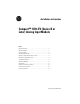
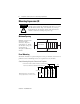
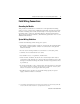
Compact™ 1769-IF4 (Series B or Later) Analog Input Module Module Description 1 2a Item Description 1 bus lever (with locking function) 2a upper panel mounting tab 2b lower panel mounting tab 3 module status LED 4 module door with terminal identification label 5a movable bus connector with female pins 5b stationary bus connector with male pins 6 nameplate label 7a upper tongue-and-groove slots 7b lower tongue-and-groove slots 8a upper DIN rail latch 8b lower DIN rail latch 9 w
Compact™ 1769-IF4 (Series B or Later) Analog Input Module 3 Module Installation Compact I/O is suitable for use in an industrial environment when installed in accordance with these instructions. Specifically, this equipment is intended for use in clean, dry environments (Pollution degree 2 (1)) and to circuits not exceeding Over Voltage Category II (2) (IEC 60664-1).
Compact™ 1769-IF4 (Series B or Later) Analog Input Module Remove Power ATTENTION ! Remove power before removing or inserting this module. When you remove or insert a module with power applied, an electrical arc may occur.
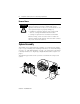
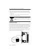
Compact™ 1769-IF4 (Series B or Later) Analog Input Module 5 1. Disconnect power. 2. Check that the bus lever of the module to be installed is in the unlocked (fully right) position. 3. Use the upper and lower tongue-and-groove slots (1) to secure the modules together (or to a controller). 4. Move the module back along the tongue-and-groove slots until the bus connectors (2) line up with each other. 5. Push the bus lever back slightly to clear the positioning tab (3).
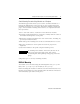
Compact™ 1769-IF4 (Series B or Later) Analog Input Module Mounting Expansion I/O ATTENTION ! During panel or DIN rail mounting of all devices, be sure that all debris (metal chips, wire strands, etc.) is kept from falling into the module. Debris that falls into the module could cause damage on power up. Minimum Spacing End Cap Compact I/O Compact I/O Compact I/O Host Controller Side Compact I/O Top Compact I/O Maintain spacing from enclosure walls, wireways, adjacent equipment, etc.
Compact™ 1769-IF4 (Series B or Later) Analog Input Module 7 Panel Mounting Procedure Using Modules as a Template The following procedure allows you to use the assembled modules as a template for drilling holes in the panel. If you have sophisticated panel mounting equipment, you can use the dimensional template provided on page 6. Due to module mounting hole tolerance, it is important to follow these procedures: 1. On a clean work surface, assemble no more than three modules. 2.
Compact™ 1769-IF4 (Series B or Later) Analog Input Module Replacing a Single Module within a System The module can be replaced while the system is mounted to a panel (or DIN rail). Follow these steps in order: 1. Remove power. See important note on page 4. 2. On the module to be removed, remove the upper and lower mounting screws from the module (or open the DIN latches using a flat-blade or phillips-style screwdriver). 3. Move the bus lever to the right to disconnect (unlock) the bus. 4.
Compact™ 1769-IF4 (Series B or Later) Analog Input Module 9 Field Wiring Connections Grounding the Module This product is intended to be mounted to a well-grounded mounting surface such as a metal panel. Additional grounding connections from the module’s mounting tabs or DIN rail (if used), are not required unless the mounting surface cannot be grounded. Refer to Industrial Automation Wiring and Grounding Guidelines, Allen-Bradley publication 1770-4.1, for additional information.
Compact™ 1769-IF4 (Series B or Later) Analog Input Module • The 1769-IF4 module does not provide loop power for analog inputs. Use a power supply that matches the input transmitter specifications. • Differential analog inputs are more immune to noise than single-ended analog inputs. • Voltages on Vin+, V/Iin-, and Iin+ of the 1769-IF4 module must be within ±10V dc of analog common. ATTENTION ! Be careful when stripping wires. Wire fragments that fall into a module could cause damage at power up.
Compact™ 1769-IF4 (Series B or Later) Analog Input Module 11 Wiring Differential Inputs Belden 8761 cable (or equivalent) – analog source + V in 0 + V/I in 0 I in 0+ ANLG Com V/I in 1 ANLG Com V/I in 2 - V in 1 + I in 1+ V in 2 + earth ground the shield locally at the module I in 2+ ANLG Com V in 3 + V/I in 3 I in 3+ ANLG Com dc NEUT +24V dc + - External 24V dc Power Supply(1) (optional)(2) (1) The external power supply must be rated Class 2, with a 24V dc range of 20.4 to 26.
Compact™ 1769-IF4 (Series B or Later) Analog Input Module Wiring Single-Ended Sensor/Transmitter Types 1769-IF4 Terminal Block Sensor/ + Transmitter Supply Current Transmitter + Signal Voltage Transmitter + Ground Signal V in 0 + V/I in 0 I in 0 + ANLG Com V in 1 + V/I in 1 I in 1 + ANLG Com V in 2 + V/I in 2 - Voltage Transmitter + Ground Signal I in 2 + ANLG Com V in 3 + V/I in 3 I in 3 + ANLG Com +24V dc dc NEUT External 24V dc + Power Supply(1) (2) (optional) (1) The external power supply
Compact™ 1769-IF4 (Series B or Later) Analog Input Module 13 Wiring Mixed Transmitter Types Single-ended Voltage Transmitter – 1769-IF4 Terminal Block Signal V in 0 + V/I in 0 - + Differential Voltage Transmitter – Supply + I in 0 + ANLG Com V in 1 + +Signal V/I in 1 - – I in 1 + ANLG Com V in 2 + V/I in 2 - – Differential Signal Current + Transmitter – Supply + I in 2 + ANLG Com V in 3 + V/I in 3 I in 3 + 2-Wire Current Transmitter Sensor/ Transmitter Supply ANLG Com +24V dc dc NEUT Sign
Compact™ 1769-IF4 (Series B or Later) Analog Input Module upper retaining screw wiring the finger-safe terminal block lower retaining screw Removing the Finger-Safe Terminal Block To remove the terminal block, loosen the upper and lower retaining screws. The terminal block will back away from the module as you remove the screws. When replacing the terminal block, torque the retaining screws to 0.46 Nm (4.1 in-lbs).
Compact™ 1769-IF4 (Series B or Later) Analog Input Module 15 Wire Size and Terminal Screw Torque Each terminal accepts up to two wires with the following restrictions: Wire Type Solid Wire Size Terminal Screw Torque Retaining Screw Torque Cu-90°C (194°F) #14 to #22 AWG 0.68 Nm (6 in-lbs) 0.46 Nm (4.1 in-lbs) Stranded Cu-90°C (194°F) #16 to #22 AWG 0.68 Nm (6 in-lbs) 0.46 Nm (4.
Compact™ 1769-IF4 (Series B or Later) Analog Input Module Configuration Data File The manipulation of the bits from this file is normally done with programming software (e.g. RSLogix 500, RSNetworx for DeviceNet, etc.) during initial configuration of the system. In that case, graphical screens are provided by the programmer to simplify configuration. However, some systems, like the 1769-ADN DeviceNet Adapter, also allow the bits to be altered as part of the control program, using communication rungs.
Compact™ 1769-IF4 (Series B or Later) Analog Input Module 17 Specifications General Specifications Specification Value Dimensions 118 mm (height) x 87 mm (depth) x 35 mm (width) height including mounting tabs is 138 mm 4.65 in. (height) x 3.43 in (depth) x 1.38 in (width) height including mounting tabs is 5.43 in. Approximate Shipping Weight (with carton) 300g (0.65 lbs.
Compact™ 1769-IF4 (Series B or Later) Analog Input Module Input Specifications Specification 1769-IF4 (Series B or later) Analog Normal Operating Ranges(1) Voltage: ± 10V dc, 0 to 10V dc, 0 to 5V dc, 1 to 5V dc Current: 0 to 20 mA, 4 to 20 mA Full Scale Analog Ranges(1) Voltage: ± 10.5V dc, -0.5 to 10.5V dc, -0.5 to 5.25V dc, 0.5 to 5.25V dc Current: 0 to 21 mA, 3.2 to 21 mA Number of Inputs 4 differential or single-ended Bus Current Draw (max.
Compact™ 1769-IF4 (Series B or Later) Analog Input Module Specification 1769-IF4 (Series B or later) Accuracy Drift with Temperature Voltage Terminal: ±0.003% per °C Current Terminal: ±0.0045% per °C 19 Optional 24V dc Class 2 Power 20.4 V to 26.4 V dc(3) Supply Voltage Range Calibration The module performs autocalibration on channel enable and on a configuration change between channels. Non-linearity (in percent full scale) ±0.03% Repeatability(1) ±0.03% Module Error over Full Voltage: ±0.
Compact™ 1769-IF4 (Series B or Later) Analog Input Module Hazardous Location Considerations This equipment is suitable for use in Class I, Division 2, Groups A, B, C, D or non-hazardous locations only. The following ATTENTION statement applies to use in hazardous locations. WARNING ! EXPLOSION HAZARD • Substitution of components may impair suitability for Class I, Division 2.
Compact™ 1769-IF4 (Series B or Later) Analog Input Module 21 For More Information For Refer to this Document Pub. No. A more detailed description of how to MicroLogix 1500 Programmable 1764-UM001A-US-P install and use your Compact I/O with Controllers User Manual MicroLogix 1500 programmable controller. Detailed information on installing, programming, and troubleshooting your Compact Analog I/O modules.
Compact™ 1769-IF4 (Series B or Later) Analog Input Module Publication 1769-IN048A-EN-P
Compact™ 1769-IF4 (Series B or Later) Analog Input Module 23 Publication 1769-IN048A-EN-P
MicroLogix and Compact are trademarks of Rockwell Automation. Belden is a trademark of Belden, Inc, Publication 1769-IN048A-EN-P - December 2000 Supersedes Publication 1769-IN0016A-EN-P - June 2000 PN 40072-103-01(A) © 2000 Rockwell International Corporation. Printed in the U.S.A.