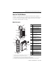
Installation Instructions Compact High-density Analog Voltage Input Module Catalog Number 1769-IF16V Topic Page Important User Information 2 Electrostatic Discharge 3 Remove Power 3 Hazardous Location 4 Environnements dangereux 4 About the 1769-IF16V Module 5 Install the 1769-IF16V Module 6 Adding the Module to the 1769 System 6 Mounting Expansion I/O 9 Making Field Wiring Connections 11 Configure the 1769-IF16V Module 15 Specifications 23 Replacement Parts 25 Additional Resour
Compact High-density Analog Voltage Input Module Important User Information Solid state equipment has operational characteristics differing from those of electromechanical equipment. Safety Guidelines for the Application, Installation and Maintenance of Solid State Controls (Publication SGI-1.1 available from your local Rockwell Automation sales office or online at http://literature.rockwellautomation.
Compact High-density Analog Voltage Input Module 3 Electrostatic Discharge ATTENTION Electrostatic discharge can damage integrated circuits or semiconductors if you touch bus connector pins. Follow these guidelines when you handle the module: • Touch a grounded object to discharge static potential. • Wear an approved wrist-strap grounding device. • Do not touch the bus connector or connector pins. • Do not touch circuit components inside the module. • Use a static-safe work station, if available.
Compact High-density Analog Voltage Input Module Hazardous Location This equipment is suitable for use in Class I, Division 2, Groups A, B, C, D or non-hazardous locations only. The following statement applies to use in hazardous locations. WARNING EXPLOSION HAZARD Substitution of components may impair suitability for Class I, Division 2. Do not replace components or disconnect equipment unless power is switched off or the area is known to be non-hazardous.
Compact High-density Analog Voltage Input Module 5 About the 1769-IF16V Module Compact I/O is suitable for use in an industrial environment when installed in accordance with these instructions. Specifically, this equipment is intended for use in clean, dry environments (Pollution degree 2(1)) and to circuits not exceeding Over Voltage Category II(2) (IEC 60664-1)(3).
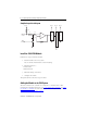
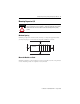
Compact High-density Analog Voltage Input Module Simplified Input Circuit Diagram VLOCAL VLOCAL VLOCAL VLOCAL 10 M 200 20 K + IN+ - Gain 0.1 μF COM 20 K M u l t i p l e x e r A/D Install the 1769-IF16V Module Follow these steps to install the module. 1. Add the module to the 1769 system. You can add the module before or after mounting. 2. Mount Expansion I/O. • Panel mount • DIN-rail mount 3. Make field wiring connections. 4. Configure the module.
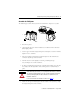
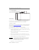
Compact High-density Analog Voltage Input Module 7 Assemble the 1769 System The following procedure shows you how to assemble the Compact I/O system. 3 4 2 1 5 1 1. Disconnect power. 2. Check that the bus lever of the module to be installed is in the unlocked (fully right) position. 3. Use the upper and lower tongue-and-groove slots (1) to secure the modules together or to a controller. 4. Move the module back along the tongue-and-groove slots until the bus connectors (2) line up with each other. 5.
Compact High-density Analog Voltage Input Module 8. Lock the end-cap bus terminator (6). IMPORTANT You must use a 1769-ECR or 1769-ECL right or left end cap to terminate the end of the serial communication bus. An I/O configuration fault will occur if an end cap is not used. Replace a Single Module Within a System The module can be replaced while the system is mounted to a panel or DIN rail. 1. Remove power. See Remove Power on page 3. 2.
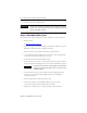
Compact High-density Analog Voltage Input Module 9 Mounting Expansion I/O ATTENTION During panel or DIN rail mounting of all devices, be sure that all debris, that is, metal chips or wire strands, is kept from falling into the module. Debris that falls into the module could cause damage when cycling power. Minimum Spacing Maintain spacing from enclosure walls, wireways, or adjacent equipment. Allow 50 mm (2 in.) of space on all sides for adequate ventilation, as shown.
Compact High-density Analog Voltage Input Module Use the Dimensional Template Spacing for single-wide modules 35 mm (1.378 in.) Spacing for one-and-a-half wide modules 52.5 mm (2.067 in.) Refer to host controller documentation for this dimension. NOTE: Overall spacing tolerance ±0.44 mm (0.016 in.) Locate holes every 17.5 mm (0.689 in.) to allow for a mix of single-wide and one-and-a-half-wide modules (for example, the 1769-OA16 module).
Compact High-density Analog Voltage Input Module 11 Mount the Module to a DIN Rail The module can be mounted using these DIN rails: • 35 x 7.5 mm (EN 50 022 - 35 x 7.5) • 35 x 15 mm (EN 50 022 - 35 x 15) To mount the module on a DIN rail, follow these steps. 1. Close the DIN rail latches. 2. Press the DIN rail mounting area of the module against the DIN rail. The latches will momentarily open and lock into place.
Compact High-density Analog Voltage Input Module System Wiring Guidelines Consider the following when wiring your system: • All module commons (COM) are connected in the analog module. • The analog common (COM) is not connected to earth ground inside the module. • Channels are not isolated from each other. • Use Belden 8761, or equivalent, shielded wire.
Compact High-density Analog Voltage Input Module 13 Wire Input Sensors/Transmitters Sensor/ + Transmitter Power(1) - 1769-IF16V Terminal Block Voltage Transmitter + Signal IN0+ IN1+ IN2+ IN3+ IN4+ IN5+ Voltage Transmitter + Ground IN6+ IN7+ Signal Com Com IN8+ IN9+ IN10+ IN11+ IN12+ IN13+ (1) The sensor power supply must be rated Class 2. IN14+ IN15+ Label the Terminals A removable, write-on label is provided with the module.
Compact High-density Analog Voltage Input Module 14 Wire the Finger-safe Terminal Block Upper Retaining Screw Lower Retaining Screw When wiring the terminal block, keep the finger-safe cover in place. 1. Loosen the terminal screws to be wired. 2. Route the wire under the terminal pressure plate. You can use the bare wire or a spade lug. The terminals will accept a 6.35 mm (0.25 in.) spade lug. TIP The terminal screws are non-captive. Therefore, it is possible to use a ring lug [maximum 1/4 inch o.d.
Compact High-density Analog Voltage Input Module 15 Configure the 1769-IF16V Module Use the following I/O memory mapping tables to configure the 1769-IF16V module. Output Data File For each module, slot x, words 0 and 1 in the output data file contain the cancel latched channel alarm control bits.
Compact High-density Analog Voltage Input Module Input Data File For each module, slot x, words 0…15 in the input data file contain the converted value of the module’s analog input channels. Word 16 in the input data file contains the time stamp value (if time stamping is enabled) that corresponds to the module's last input data sampling period. Words 17…21 in the input data file contain status bits for the analog input channels.
Compact High-density Analog Voltage Input Module 17 The bits are defined as follows: • • • • • • • SGN = Sign bit in 2’s complement format. Nu = Not Used. Bit set to 0. Sx = General Status bit for input channels 0…15. Ox = Over range flag bits for input channels 0…15. Ux = Under range flag bits for input channels 0…15. Hx = High Alarm flag bits for input channels 0…15. Lx = Low Alarm flag bits for input channels 0…15.
Compact High-density Analog Voltage Input Module Configuration Data Array Word/Bit 15 14 13 Word 14 EC Reserved Word 15 Reserved Word 16 SGN Process Alarm High Data Value Channel 2 Word 17 SGN Process Alarm Low Data Value Channel 2 Word 18 SGN Alarm Dead Band Value Channel 2 Word 19 Reserved Word 20 EC Word 21 Reserved Word 22 SGN Process Alarm High Data Value Channel 3 Word 23 SGN Process Alarm Low Data Value Channel 3 Word 24 SGN Alarm Dead Band Value Channel 3 Word 25
Compact High-density Analog Voltage Input Module 19 Configuration Data Array Word/Bit 15 14 13 Word 38 EC Reserved Word 39 Reserved Word 40 SGN Process Alarm High Data Value Channel 6 Word 41 SGN Process Alarm Low Data Value Channel 6 Word 42 SGN Alarm Dead Band Value Channel 16 Word 43 Reserved Word 44 EC Word 45 Reserved Word 46 SGN Process Alarm High Data Value Channel 7 Word 47 SGN Process Alarm Low Data Value Channel 7 Word 48 SGN Alarm Dead Band Value Channel 7 Word 4
Compact High-density Analog Voltage Input Module Configuration Data Array Word/Bit 15 14 13 Word 62 EC Reserved Word 63 Reserved Word 64 SGN Process Alarm High Data Value Channel 10 Word 65 SGN Process Alarm Low Data Value Channel 10 Word 66 SGN Alarm Dead Band Value Channel 10 Word 67 Reserved Word 68 EC Word 69 Reserved Word 70 SGN Process Alarm High Data Value Channel 11 Word 71 SGN Process Alarm Low Data Value Channel 11 Word 72 SGN Alarm Dead Band Value Channel 11 W
Compact High-density Analog Voltage Input Module 21 Configuration Data Array Word/Bit 15 14 13 12 11 Word 86 EC Reserved Word 87 Reserved Word 88 SGN Process Alarm High Data Value Channel 14 Word 89 SGN Process Alarm Low Data Value Channel 14 Word 90 SGN Alarm Dead Band Value Channel 14 Word 91 Reserved Word 92 EC Word 93 Reserved Word 94 SGN Process Alarm High Data Value Channel 15 Word 95 SGN Process Alarm Low Data Value Channel 15 Word 96 SGN Alarm Dead Band Value Chann
Compact High-density Analog Voltage Input Module Bit Definitions for Channel Configuration Words Define To Choose Make these bit settings 15 Input Filter Selection 14 13 12 11 10 09 08 07 06 05 04 02 01 00 60 Hz 0 0 0 0 50 Hz 0 0 0 1 16 Hz 0 0 1 0 315 Hz 0 0 1 1 0 1 0 0 1365 Hz Enable Enable 1 Interrupt(1) Disable 0 Process Alarm Latch Enable 1 Disable 0 Enable Process Alarms Enable 1 Disable 0 Enable Channel Enable 1 Disable 0 (1) 03 Ala
Compact High-density Analog Voltage Input Module 23 Specifications Compact High Density Analog Voltage Input Module - 1769-IF16V Attribute Value Dimensions (HxWxD), approx. 118 mm x 87 mm x 35 mm Height including mounting tabs is 138 mm (5.43 in.) 4.65 in. x 3.43 in. x 1.38 in. Height including mounting tabs is 138 mm (5.43 in.) Weight, approx. (with carton) 281 g (0.
Compact High-density Analog Voltage Input Module Input Specifications Attribute Value (1) Analog normal operating ranges (1) Full scale analog ranges ±10V DC, 0 …10V DC, 0…5V DC, 1…5V DC ±10.5V DC, -0.5…10.5V DC, -0.5…5.25V DC, 0.5…5.25V DC Number of inputs 16 single-ended Converter type Sigma Delta Response speed per channel Input filter and configuration dependent.
Compact High-density Analog Voltage Input Module 25 Certifications Certification Agency certification Value • C-UL certified (under CSA C22.2 No. 142) • UL 508 listed • CE compliant for all applicable directives Hazardous environment class Class I, Division 2, Hazardous Location, Groups A, B, C, D (UL 1604, C-UL under CSA C22.2 No.
Compact High-density Analog Voltage Input Module Additional Resources For more information refer to the following publications. Resource Description Compact High-Density Analog Input Modules User Manual, publication 1769-UM018. Detailed description of how to install , operate, and troubleshoot your Compact I/O module. 1768 CompactLogix Controllers User Manual, publication 1768-UM001 Detailed description of how to install and use your 1768 CompactLogix controller.
Compact High-density Analog Voltage Input Module 27 Notes: Publication 1769-IN086A-EN-P - August 2008
Allen-Bradley, Rockwell Automation, Compact, CompactLogix, MicroLogix, RSLogix 500, and RSNetWorx for DeviceNet are trademarks of Rockwell Automation, Inc. Trademarks not belonging to Rockwell Automation are property of their respective companies. Publication 1769-IN086A-EN-P - August 2008 PN-28832 Copyright © 2008 Rockwell Automation, Inc. All rights reserved. Printed in the U.S.A.