
User Manual
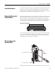
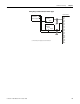
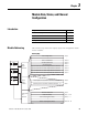
Table Of Contents
- 1769-UM018A-EN-P, Compact High-density Analog Input Modules
- Table of Contents
- Preface
- 1 - Overview
- 2 - Installation and Wiring
- 3 - Module Data, Status, and Channel Configuration
- 4 - Module Diagnostics and Troubleshooting
- A - Specifications
- B - Module Addressing and Configuration with MicroLogix 1500 Controller
- C - Configuration Using the RSLogix 5000 Generic Profile for CompactLogix Controllers
- D - Two’s Complement Binary Numbers
- Glossary
- Index
- Back Cover
Publication 1769-UM018A-EN-P - October 2008 27
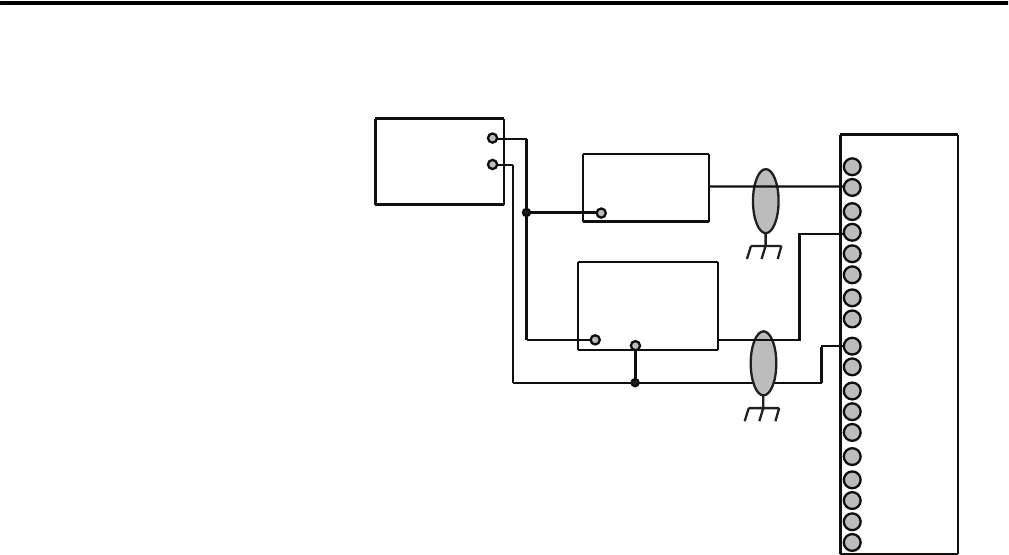
Installation and Wiring Chapter 2
Wiring Single-ended Sensor/Transmitter Types
+
IN1+
IN0+
IN3+
IN2+
IN5+
IN4+
IN7+
IN8+
IN6+
IN9+
IN11+
IN10+
IN12+
IN13+
IN15+
IN14+
Com
Com
+
+
-
Current or Voltage
Transmitter
Sensor/
Transmitter
Power
Supply
(1)
Current or Voltage
Transmitter
Signal
Signal
Ground
Terminal Block
(1) The sensor power supply must be rated Class 2.