
User Manual
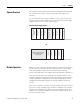
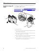

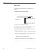
Table Of Contents
- 1769-UM018A-EN-P, Compact High-density Analog Input Modules
- Table of Contents
- Preface
- 1 - Overview
- 2 - Installation and Wiring
- 3 - Module Data, Status, and Channel Configuration
- 4 - Module Diagnostics and Troubleshooting
- A - Specifications
- B - Module Addressing and Configuration with MicroLogix 1500 Controller
- C - Configuration Using the RSLogix 5000 Generic Profile for CompactLogix Controllers
- D - Two’s Complement Binary Numbers
- Glossary
- Index
- Back Cover
18 Publication 1769-UM018A-EN-P - October 2008
Chapter 2 Installation and Wiring
Mount to a Panel
Mount the module to a panel using two screws per module. Use M4
or #8 panhead screws. Mounting screws are required on every
module.
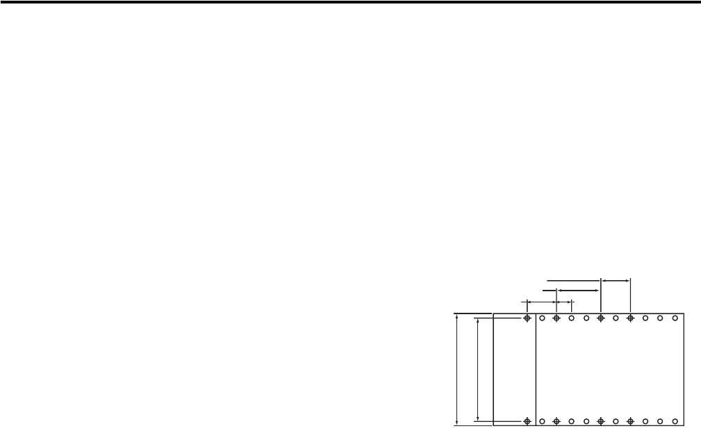
Panel Mounting Using the Dimensional Template
Locate holes every 17.5 mm (0.689 in.) to allow for a mix of
single-wide and one-and-a-half-wide modules (for example, the
1769-OA16 module).
Panel Mounting Using the Modules as a Template
This procedure lets you to use the assembled modules as a template
for drilling holes in the panel. If you have sophisticated
panel-mounting equipment, you can use the dimensional template
provided. Due to module mounting hole tolerance, it is important to
follow these procedures.
1. On a clean work surface, assemble no more than three modules.
2. Using the assembled modules as a template, carefully mark the
center of all module-mounting holes on the panel.
3. Return the assembled modules to the clean work surface,
including any previously mounted modules.
4. Drill and tap the mounting holes for the recommended M4 or #8
screw.
5. Place the modules back on the panel, and check for proper hole
alignment.
l Mounting
Host Controller
Refer to host controller documentation for this dimension.
Spacing for single-wide modules 35 mm (1.378 in.).
Overall hole spacing tolerance:
±0.4 mm (0.016 in.).
Spacing for one-and-a-half-wide modules 52.5 mm (2.067 in.).