
User Manual
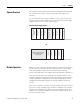
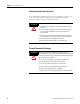
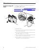

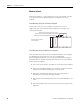
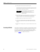
Table Of Contents
- 1769-UM018A-EN-P, Compact High-density Analog Input Modules
- Table of Contents
- Preface
- 1 - Overview
- 2 - Installation and Wiring
- 3 - Module Data, Status, and Channel Configuration
- 4 - Module Diagnostics and Troubleshooting
- A - Specifications
- B - Module Addressing and Configuration with MicroLogix 1500 Controller
- C - Configuration Using the RSLogix 5000 Generic Profile for CompactLogix Controllers
- D - Two’s Complement Binary Numbers
- Glossary
- Index
- Back Cover
16 Publication 1769-UM018A-EN-P - October 2008
Chapter 2 Installation and Wiring
Assemble the Compact I/O
System
The module can be attached to the controller or an adjacent I/O
module before or after mounting.
For mounting instructions, see Panel Mounting Using the Dimensional
Template on page 18, or Mount to a DIN Rail on page 19. To work
with a system that is already mounted, see Replace a Single Module
Within a System on page 19.
1. Disconnect power.
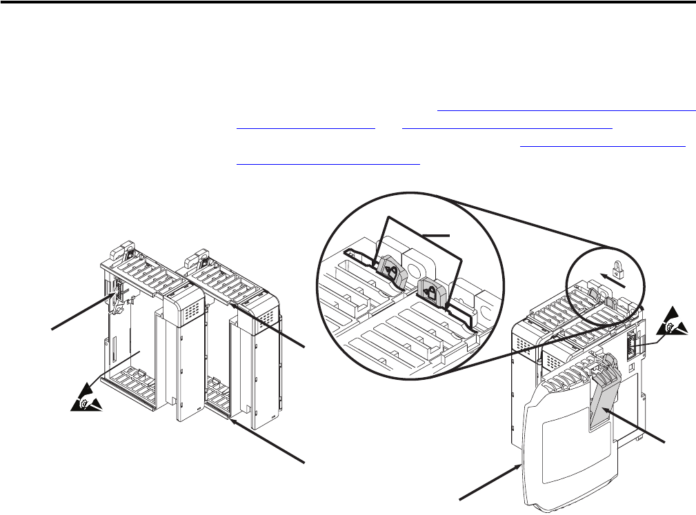
2. Check that the bus lever of the module to be installed is in the
unlocked (fully right) position.
3. Use the upper and lower tongue-and-groove slots (1) to secure
the modules together (or to a controller).
4. Move the module back along the tongue-and-groove slots until
the bus connectors (2) line up with each other.
5. Use your fingers or a small screwdriver to push the bus lever
back slightly to clear the positioning tab (3).
6
5
4
3
1
1
2