
User Manual

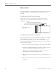
Table Of Contents
- 1769-UM018A-EN-P, Compact High-density Analog Input Modules
- Table of Contents
- Preface
- 1 - Overview
- 2 - Installation and Wiring
- 3 - Module Data, Status, and Channel Configuration
- 4 - Module Diagnostics and Troubleshooting
- A - Specifications
- B - Module Addressing and Configuration with MicroLogix 1500 Controller
- C - Configuration Using the RSLogix 5000 Generic Profile for CompactLogix Controllers
- D - Two’s Complement Binary Numbers
- Glossary
- Index
- Back Cover
14 Publication 1769-UM018A-EN-P - October 2008
Chapter 2 Installation and Wiring
Hazardous Location Considerations
This equipment is suitable for use in Class I, Division 2, Groups A, B,
C, D or non-hazardous locations only. The following attention
statement applies to use in hazardous locations.
Prevent Electrostatic Discharge
ATTENTION
EXPLOSION HAZARD
• Substitution of components may impair suitability for Class I,
Division 2.
• Do not replace components or disconnect equipment unless
power has been switched off or the area is known to be
non-hazardous.
• Do not connect or disconnect components unless power has
been switched off or the area is known to be non-hazardous.
• This product must be installed in an enclosure.
• All wiring must comply with N.E.C. article 501-4(b).
ATTENTION
Electrostatic discharge can damage integrated circuits or
semiconductors if you touch analog I/O module bus connector pins
or the terminal block on the input module. Follow these guidelines
when you handle the module:
• Touch a grounded object to discharge static potential.
• Wear an approved wrist-strap grounding device.
• Do not touch the bus connector or connector pins.
• Do not touch circuit components inside the module.
• Use a static-safe work station, if available.
• When it is not in use, keep the module in its static-shield box.