Compact High-density Analog Input Modules User Manual (Catalog Numbers 1769-IF16C, 1769-IF16V)
Important User Information Solid state equipment has operational characteristics differing from those of electromechanical equipment. Safety Guidelines for the Application, Installation and Maintenance of Solid State Controls (publication SGI-1.1 available from your local Rockwell Automation sales office or online at http://literature.rockwellautomation.com) describes some important differences between solid state equipment and hard-wired electromechanical devices.
Table of Contents Preface Introduction . . . . . . . . . . . . . . . . About this Publication . . . . . . . . . Who Should Use This Publication Additional Resources. . . . . . . . . . Conventions . . . . . . . . . . . . . . . . . . . . . . . . . . . . . . . . . . . . . . . . . . . . . . . . . . . . . . . . . . . . . . . . . . . . . . . . . . . . . . . . . . . . . . . . . . . . . . . . . . . . . . . . . . . . . . . . . . . . . . . . . 7 7 7 8 8 . . . . . . . . . . . . . . . . . . .
Table of Contents Input Data File . . . . . . . . . . . . . . . . . Time Stamp Value (Word 16) . . . . General Status Bits (S0…S15) . . . . Low Alarm Flag Bits (L0 …L15) . . High Alarm Flag Bits (H0…H15). . Over-Range Flag Bits (O0…O15) . Under-Range Flag Bits (U0…U15). Output Data File . . . . . . . . . . . . . . . . Configuration Data File . . . . . . . . . . . Channel Configuration . . . . . . . . . Enable/Disable Channel (EC) . . . . Input Filter Selection . . . . . . . . . .
Table of Contents Appendix A Specifications Introduction . . . . . . . . General Specifications . Input Specifications. . . Certifications. . . . . . . . Replacement Parts. . . . . . . . . . . . . . . . . . . . . . . . . . . . . . . . . . . . . . . . . . . . . . . . . . . . . . . . . . . . . . . . . . . . . . . . . . . . . . . . . . . . . . . . . . . . . . . . . . . . . . . . . . . . . . . . . . . . . . . . . . . . . . . . . . . . . . .. .. .. .. ..
Table of Contents 6 Publication 1769-UM018A-EN-P - October 2008
Preface Introduction Read this preface to familiarize yourself with the rest of the manual. Topic About this Publication Page About this Publication 7 Who Should Use This Publication 7 Additional Resources 8 Conventions 8 This manual is a guide for using Compact High Density Analog Input Modules, catalog numbers 1769-IF16C and 1769-IF16V. It describes the procedures you use to configure, operate, and troubleshoot your module.
Preface Additional Resources These documents contain additional information about control systems that use Compact I/O modules. Resource Description MicroLogix 1500 User Manual, publication 1764-UM001 A user manual containing information on how to install, use and program your MicroLogix 1500 controller. DeviceNet Adapter User Manual, publication 1769-UM001 A user manual containing information on how to install, and use your 1769-ADN DeviceNet adapter.
Chapter 1 Overview Introduction Topic Module Description Page Module Description 9 System Overview 11 Module Operation 11 The modules convert and digitally store analog data for retrieval by controllers, such as the CompactLogix or MicroLogix 1500 controllers. The modules provide the following input types and ranges. Normal and Full Ranges Cat. No. Normal Operating Input Range Full Module Range 1769-IF16V ±10V DC ± 10.5V DC 1…5V DC 0.5…5.25V DC 0…5V DC -0.5…+5.25V DC 0…10V DC -0.
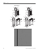
Chapter 1 Overview Hardware Features 1 2a 1 2a 3 OK 3 OK Analog Analog DANGER DANGER Do Not Remove RTB Under Power Unless Area is Non-Hazardous 10a Do Not Remove RTB Under Power Unless Area is Non-Hazardous 10a IN0+ IN1+ IN2+ IN0+ IN1+ IN2+ IN3+ IN3+ IN4+ IN4+ IN5+ IN5+ IN6+ IN6+ IN7+ 10 IN7+ 10 COM COM IN8+ COM COM IN8+ IN9+ IN9+ IN10+ IN10+ IN11+ IN11+ IN12+ IN12+ IN13+ 10b IN14+ IN15+ Ensure Adjacent Bus Lever is Unlatched/Latched Before/After Removing/Inserting M
Overview System Overview Chapter 1 The modules communicate to the controller through the bus interface. The modules also receive 5 and 24V DC power through the bus interface. You can install as many analog modules as your power supply can support. However, the modules may not be located more than eight modules away from the system power supply.
Chapter 1 Overview The channel status words are described in the Input Data File on page 31. The controller reads the two’s complement binary converted analog data from the modules. This typically occurs at the end of the program scan or when commanded by the control program. If the controller and the modules determine that the bus data transfer was made without error, the data is used in your control program. No field calibration is required.
Chapter 2 Installation and Wiring Introduction Topic General Considerations Page General Considerations 13 Assemble the Compact I/O System 16 Mounting the Module 17 Replace a Single Module Within a System 19 Grounding the Module 20 System Wiring Guidelines 21 Label the Terminals 23 Remove the Finger-safe Terminal Block 23 Wire the Finger-safe Terminal Block 23 Wire the Modules 25 The Compact I/O system is suitable for use in an industrial environment when installed in accordance wi
Chapter 2 Installation and Wiring Hazardous Location Considerations This equipment is suitable for use in Class I, Division 2, Groups A, B, C, D or non-hazardous locations only. The following attention statement applies to use in hazardous locations. ATTENTION EXPLOSION HAZARD • Substitution of components may impair suitability for Class I, Division 2. • Do not replace components or disconnect equipment unless power has been switched off or the area is known to be non-hazardous.
Installation and Wiring Chapter 2 Remove Power ATTENTION Remove power before removing or inserting this module. When you remove or insert a module with power applied, an electrical arc may occur. An electrical arc can cause personal injury or property damage by: • sending an erroneous signal to your system’s field devices, causing unintended machine motion. • causing an explosion in a hazardous environment.
Chapter 2 Installation and Wiring Assemble the Compact I/O System The module can be attached to the controller or an adjacent I/O module before or after mounting. For mounting instructions, see Panel Mounting Using the Dimensional Template on page 18, or Mount to a DIN Rail on page 19. To work with a system that is already mounted, see Replace a Single Module Within a System on page 19. 3 4 2 1 6 1 5 1. Disconnect power. 2.
Installation and Wiring Chapter 2 6. To allow communication between the controller and module, move the bus lever fully to the left (4) until it clicks. Make sure it is locked firmly in place. ATTENTION When attaching I/O modules, it is very important that the bus connectors are securely locked together to be sure of proper electrical connection. 7. Attach an end cap terminator (5) to the last module in the system by using the tongue-and-groove slots as before. 8. Lock the end cap bus terminator (6).
Chapter 2 Installation and Wiring Mount to a Panel Mount the module to a panel using two screws per module. Use M4 or #8 panhead screws. Mounting screws are required on every module. Panel Mounting Using the Dimensional Template Locate holes every 17.5 mm (0.689 in.) to allow for a mix of single-wide and one-and-a-half-wide modules (for example, the 1769-OA16 module). Overall hole spacing tolerance: ±0.4 mm (0.016 in.). Host Controller Spacing for single-wide modules 35 mm (1.378 in.).
Installation and Wiring Chapter 2 6. Attach the modules to the panel using the mounting screws. TIP If mounting more modules, mount only the last one of this group and put the others aside. This reduces remounting time during drilling and tapping of the next group. 7. Repeat steps 1…6 for any remaining modules. Mount to a DIN Rail The module can be mounted using the following DIN rails: 35 x 7.5 mm (EN 50 022 - 35 x 7.5) or 35 x 15 mm (EN 50 022 - 35 x 15).
Chapter 2 Installation and Wiring 5. Gently slide the disconnected module forward. If you feel excessive resistance, check that the module has been disconnected from the bus, and that both mounting screws have been removed or DIN latches opened. TIP It may be necessary to rock the module slightly from front to back to remove it, or, in a panel-mounted system, to loosen the screws of adjacent modules. 6.
Installation and Wiring System Wiring Guidelines Chapter 2 Consider the following when wiring your system: • All module commons (COM) are connected in the analog module. • The analog common (COM) is not connected to earth ground inside the module. • Channels are not isolated from each other. • To ensure optimum accuracy, limit overall cable impedance by keeping your cable as short as possible. Locate the I/O system as close to your sensors or actuators as your application will permit.
Chapter 2 Installation and Wiring Voltage Input Accuracy Rs Rc + Vs V in Ri - Rc Where: Rc = DC resistance of the cable (each conductor) depending on cable length Rs = Source impedance of analog transducer/sensor input Ri = Impedance of the voltage input (1 MΩ for 1769-IF16V module) Vs = Voltage source (voltage at the transducer/sensor input device) Vin = Measured potential at the module input %Ai = Percent added inaccuracy in a voltage-based system due to source and cable impedance.
Installation and Wiring Chapter 2 Label the Terminals A removable, write-on label is provided with the module. Remove the label from the door, mark the identification of each terminal with permanent ink, and slide the label back into the door. Your markings (ID tag) will be visible when the module door is closed. Remove the Finger-safe Terminal Block When wiring field devices to the module, it is not necessary to remove the terminal block.
Chapter 2 Installation and Wiring 1. Loosen the terminal screws to be wired. 2. Begin wiring at the bottom of the terminal block and move up. 3. Route the wire under the terminal pressure plate. You can use the bare wire or a spade lug. The terminals accept a 6.35 mm (0.25 in.) spade lug. TIP The terminal screws are non-captive. Therefore, it is possible to use a ring lug (maximum 1/4 in. o.d. with a 0.139 in. minimum i.d. (M3.5)) with the module. 4.
Installation and Wiring Chapter 2 Wire the Modules ATTENTION To prevent shock hazard, care should be taken when wiring the module to analog signal sources. Before wiring any analog module, disconnect power from the system power supply and from any other source to the analog module. After the analog module is properly installed, follow the wiring procedure below. To ensure proper operation and high immunity to electrical noise, always use Belden 8761 (shielded, twisted-pair) or equivalent wire.
Chapter 2 Installation and Wiring 3. At one end of the cable, twist the drain wire and foil shield together. Under normal conditions, this drain wire and shield junction must be connected to earth ground, via a panel or DIN rail mounting screw at the analog I/O module end. Keep the length of the drain wire as short as possible. In environments where high frequency noise may be present, it may be necessary to also ground the cable shields to earth via a 0.1 µF capacitor at the sensor end. 4.
Installation and Wiring Chapter 2 Wiring Single-ended Sensor/Transmitter Types Terminal Block Sensor/ + Transmitter Power Supply(1) Current or Voltage Transmitter + Signal Current or Voltage Transmitter + Ground Signal IN0+ IN1+ IN2+ IN3+ IN4+ IN5+ IN6+ IN7+ Com Com IN8+ IN9+ IN10+ IN11+ IN12+ IN13+ (1) The sensor power supply must be rated Class 2.
Chapter 2 28 Installation and Wiring Publication 1769-UM018A-EN-P - October 2008
Chapter 3 Module Data, Status, and Channel Configuration Introduction Topic Module Addressing Page Module Addressing 29 Input Data File 31 Output Data File 33 Configuration Data File 34 This memory map shows the output, input, and configuration tables for the modules.
Chapter 3 Module Data, Status, and Channel Configuration Input Image The input image file represents data words and status bits. Input words 0…15 hold the input data that represents the value of the analog inputs for channels 0…15. These data words are valid only when the channel is enabled and there are no errors. If time stamping is enabled, Word 16 in the input data file contains the time stamp value that corresponds to the module's last input data sampling period.
Module Data, Status, and Channel Configuration Chapter 3 Some systems, like the 1769-ADN DeviceNet adapter system, also allow the bits to be altered as part of the control program using communication rungs. In that case, it is necessary to understand the bit arrangement. Not all controllers support program access to the configuration file. Refer to your controller’s user manual.
Chapter 3 Module Data, Status, and Channel Configuration Time Stamp Value (Word 16) The modules support a 15-bit rolling timestamp that is updated during each new update of the analog input values. The timestamp has a 1 ms resolution. If the timestamp function is enabled, the timestamp value is placed in the Input Data file, word 16, following each module conversion cycle. Enable and/or disable this timestamp in word 1, bit 15 of the Configuration Data file.
Module Data, Status, and Channel Configuration Chapter 3 Over-Range Flag Bits (O0…O15) Over-range bits for channels 0…15 are contained in Words 18…21, bits 0, 4, 8, and 12. When set (1), this bit indicates an input signal is beyond the normal operating range. For the 1769-IF16V module, it may also indicate an open circuit condition. However, the module continues to convert analog data to the maximum full range value.
Chapter 3 Module Data, Status, and Channel Configuration Configuration Data File Word/Bit 15 14 Word 0 0 Real Time Sample Value Word 1 ETS Reserved Word 2 EC Reserved Word 3 Reserved Word 4 SGN Process Alarm High Data Value Channel 0 Word 5 SGN Process Alarm Low Data Value Channel 0 Word 6 SGN Alarm Dead Band Value Channel 0 Word 7 Reserved Word 8 EC Word 9 Reserved Word 10 SGN Process Alarm High Data Value Channel 1 Word 11 SGN Process Alarm Low Data Value Channel 1 Wo
Module Data, Status, and Channel Configuration Word/Bit 15 14 13 12 11 10 09 Word 26 EC Reserved EA AL Word 27 Reserved Word 28 SGN Process Alarm High Data Value Channel 4 Word 29 SGN Process Alarm Low Data Value Channel 4 Word 30 SGN Alarm Dead Band Value Channel 4 Word 31 Reserved Word 32 EC Word 33 Reserved Word 34 SGN Process Alarm High Data Value Channel 5 Word 35 SGN Process Alarm Low Data Value Channel 5 Word 36 SGN Alarm Dead Band Value Channel 5 Word 37 Rese
Chapter 3 Module Data, Status, and Channel Configuration Word/Bit 15 14 Word 56 EC Reserved Word 57 Reserved Word 58 SGN Process Alarm High Data Value Channel 9 Word 59 SGN Process Alarm Low Data Value Channel 9 Word 60 SGN Alarm Dead Band Value Channel 9 Word 61 Reserved Word 62 EC Word 63 Reserved Word 64 SGN Process Alarm High Data Value Channel 10 Word 65 SGN Process Alarm Low Data Value Channel 10 Word 66 SGN Alarm Dead Band Value Channel 10 Word 67 Reserved Word 68
Module Data, Status, and Channel Configuration Word/Bit 15 14 13 12 11 10 09 Word 86 EC Reserved EA AL Word 87 Reserved Word 88 SGN Process Alarm High Data Value Channel 14 Word 89 SGN Process Alarm Low Data Value Channel 14 Word 90 SGN Alarm Dead Band Value Channel 14 Word 91 Reserved Word 92 EC Word 93 Reserved Word 94 SGN Process Alarm High Data Value Channel 15 Word 95 SGN Process Alarm Low Data Value Channel 15 Word 96 SGN Alarm Dead Band Value Channel 15 Word 97
Chapter 3 Module Data, Status, and Channel Configuration Channel Configuration Each channel is independently configured via a group of six consecutive words in the Configuration Data file. The first two words of the group consist of bit fields, the settings of which determine how the channel operates. See the tables below and the descriptions that follow for valid configuration settings and their meanings. The default bit status of the configuration file is all zeros.
Module Data, Status, and Channel Configuration Chapter 3 1769-IF16V Module: Bit Definitions for Input Range and Input Data Configuration Words Define To Choose Make these bit settings 15 Input Range Select Input Data Format Select 14 13 12 11 10 09 08 03 02 01 00 -10…+10V 0 0 0 0 0…5V 0 0 0 1 0…10V 0 0 1 0 1…5V 0 0 1 1 Proportional Counts 0 0 0 Engineering Units 0 0 1 Scaled for PID 0 1 0 Percent Range 0 1 1 07 06 05 04 Enable/Disable Channel (EC) Th
Chapter 3 Module Data, Status, and Channel Configuration Common Mode Rejection is better than 60 dB at 50 and 60 Hz, with the 50 and 60 Hz filters selected, respectively. The modules perform well in the presence of common mode noise as long as the signals applied to the IN+ and COM input terminals do not exceed the working voltage rating of the module. Improper earth ground may be a source of common mode noise.
Module Data, Status, and Channel Configuration Chapter 3 Module update time is calculated by adding up all of the input pair update times. This table shows the input pair update times when the lowest filter setting for the input pair is as shown. The table also shows the module update time assuming all input pairs have at least one channel enabled and the lowest filter setting is the same for each input pair.
Chapter 3 Module Data, Status, and Channel Configuration Engineering Units The module scales the analog input data to the actual current or voltage values for the selected input range. The resolution of the engineering units is 0.001V or 0.001 mA per count. Scaled-for-PID The value presented to the controller is a signed integer with zero representing the lower limit of the normal operating range and 16,383 representing the upper limit of the normal operating range.
Module Data, Status, and Channel Configuration Chapter 3 Real Time Sampling This parameter instructs the module how often to initiate a conversion cycle that will convert each enabled input channel and then place that data into the Input Data file. A conversion cycle is defined as the sequential conversion of each input pair that has at least one of its channels enabled. When the module has performed a conversion on each of the input pairs, it is ready to begin the next conversion cycle.
Chapter 3 Module Data, Status, and Channel Configuration When time stamping is enabled, the module provides a rolling time stamp value of 0…32,767 with each count representing 1 ms. When the time stamp count reaches 32,767, the value is reset to 0 and continues to increment one count every millisecond. When enabled, the Input Data file is updated with the latest time stamp value which corresponds to the end of each module conversion cycle.
Module Data, Status, and Channel Configuration Chapter 3 Alarm Deadband You may configure an alarm deadband to work with the process alarms. The deadband lets the process alarm status bit remain set, despite the alarm condition disappearing, as long as the input data remains within the deadband of the process alarm. This illustration shows an example of input data that sets each of the two alarms at some point during module operation.
Chapter 3 46 Module Data, Status, and Channel Configuration Publication 1769-UM018A-EN-P - October 2008
Chapter 4 Module Diagnostics and Troubleshooting Introduction Topic Safety Considerations Page Safety Considerations 47 Power Cycle Diagnostics 48 Channel Diagnostics 49 Non-critical vs. Critical Module Errors 50 Module Error Definition Table 50 Error Codes 51 Module Inhibit Function 57 Contacting Rockwell Automation 57 Safety considerations are an important element of proper troubleshooting procedures.
Chapter 4 Module Diagnostics and Troubleshooting Stand Clear of the Machine When troubleshooting any system problem, have all personnel remain clear of the machine. The problem could be intermittent, and sudden unexpected machine motion could occur. Have someone ready to operate an emergency stop switch in case it becomes necessary to shut off power to the machine.
Module Diagnostics and Troubleshooting Channel Diagnostics Chapter 4 When an input channel is enabled, the modules perform a diagnostic check to see that the channel has been properly configured. In addition, the modules check each channel during every conversion cycle for over-range and under-range, high and low process alarm conditions, and open-circuit conditions.
Chapter 4 Module Diagnostics and Troubleshooting Non-critical vs. Critical Module Errors Non-critical module errors are typically recoverable. Channel errors (over-range or under-range errors, process alarms, and open circuit errors) are non-critical. Non-critical errors are indicated in the module input data table. Critical module errors are conditions that prevent normal or recoverable operation of the system.
Module Diagnostics and Troubleshooting Chapter 4 Extended Error Information Field Depending upon the value in the module error field, the extended error information field can contain error codes that are module-specific or common to all 1769 analog modules. If no errors are present in the module error field, the extended error information field will be set to zero. TIP Error Codes Error codes can help troubleshoot your module.
Chapter 4 Module Diagnostics and Troubleshooting Extended Error Codes for Configuration Errors Module Error Code Extended Error Information Code Binary Binary X404 010 0 0000 0100 Invalid input range selected (channel 3) X405 010 0 0000 0101 Invalid input range selected (channel 4) X406 010 0 0000 0110 Invalid input range selected (channel 5) X407 010 0 0000 0111 Invalid input range selected (channel 6) X408 010 0 0000 1000 Invalid input range selected (channel 7) X409 010 0 0000
Module Diagnostics and Troubleshooting Chapter 4 Extended Error Codes for Configuration Errors Module Error Code Extended Error Information Code Binary Binary X404 010 0 0000 0100 Invalid input range selected (channel 3) X405 010 0 0000 0101 Invalid input range selected (channel 4) X406 010 0 0000 0110 Invalid input range selected (channel 5) X407 010 0 0000 0111 Invalid input range selected (channel 6) X408 010 0 0000 1000 Invalid input range selected (channel 7) X409 010 0 0000
Chapter 4 Module Diagnostics and Troubleshooting Extended Error Codes for Configuration Errors Module Error Code Extended Error Information Code Binary Binary X426 010 0 0010 0110 Invalid input format selected (channel 5) X427 010 0 0010 0111 Invalid input format selected (channel 6) X428 010 0 0010 1000 Invalid input format selected (channel 7) X429 010 0 0010 1001 Invalid input format selected (channel 8) X42A 010 0 0010 1010 Invalid input format selected (channel 9) X42B 010 0
Module Diagnostics and Troubleshooting Chapter 4 Extended Error Codes for Configuration Errors Module Error Code Extended Error Information Code Binary Binary X448 010 0 0100 1000 Invalid alarm data (channel 7) X449 010 0 0100 1001 Invalid alarm data (channel 8) X44A 010 0 0100 1010 Invalid alarm data (channel 9) X44B 010 0 0100 1011 Invalid alarm data (channel 10) X44C 010 0 0100 1100 Invalid alarm data (channel 11) X44D 010 0 0100 1101 Invalid alarm data (channel 12) X44E 01
Chapter 4 Module Diagnostics and Troubleshooting Invalid Input Format Selected These error codes occur when the 3-bit input format code for the indicated channel is not one of the assigned input format codes for the module. See 1769-IF16C Module: Bit Definitions for Input Range and Input Data Configuration Words on page 38 or 1769-IF16V Module: Bit Definitions for Input Range and Input Data Configuration Words on page 39 for details on the assigned input format codes for each module.
Module Diagnostics and Troubleshooting Chapter 4 Invalid Real Time Sample Value This error code occurs when the data entered for the Real Time Sample value is less than 0, is greater than 5000 (decimal) or, if non-zero, is less than the calculated module update time. See Real Time Sampling on page 43 for details on how the calculated module update time can affect the minimum allowed real time sample value. Module Inhibit Function CompactLogix controllers support the module inhibit function.
Chapter 4 58 Module Diagnostics and Troubleshooting Publication 1769-UM018A-EN-P - October 2008
Appendix A Specifications Introduction Topic Page General Specifications 59 Input Specifications 60 Certifications 61 Replacement Parts 61 General Specifications Attribute Value Dimensions (HxWxD), approx. 118 mm x 87 mm x 35 mm (4.65 in. x 3.43 in. x 1.38 in.) Height including mounting tabs is 138 mm (5.43 in.) Shipping weight, approx. (with carton) 281 g (0.
Appendix A Specifications Input Specifications Attribute 1769-IF16C 1769-IF16V Analog normal operating ranges(1) 0…20 mA, 4…20 mA ±10V DC, 0 …10V DC, 0…5V DC, 1…5V DC Full scale analog ranges(1) 0…21 mA, 3.2…21 mA ±10.5V DC, -0.5…10.5V DC, -0.5…5.25V DC, 0.5…5.25V DC Number of inputs 16 single-ended Converter type Sigma Delta Response speed per channel Input filter and configuration dependent.
Specifications Certifications Appendix A Certification Value Agency Certification C-UL certified (under CSA C22.2 No. 142) UL 508 listed CE compliant for all applicable directives Hazardous Environment Class Class I, Division 2, Hazardous Location, Groups A, B, C, D (UL 1604, C-UL under CSA C22.2 No.
Appendix A 62 Specifications Publication 1769-UM018A-EN-P - October 2008
Appendix B Module Addressing and Configuration with MicroLogix 1500 Controller Introduction Topic Page Module Input Image 63 Module Configuration File 64 Configure Analog I/O Modules in a MicroLogix 1500 System 64 This appendix examines the modules’ addressing scheme and describes module configuration using RSLogix 500 software and a MicroLogix 1500 controller. Module Input Image The modules’ input image file represents data words and status bits.
Appendix B Module Addressing and Configuration with MicroLogix 1500 Controller Module Configuration File The configuration file contains information that you use to define the way a specific channel functions. The configuration file is explained in more detail in Chapter 3. The configuration file is modified using the programming software configuration screen. For an example of module configuration using RSLogix 500 software, see Configure Analog I/O Modules in a MicroLogix 1500 System.
Module Addressing and Configuration with MicroLogix 1500 Controller Appendix B If you have a version of RSLogix 500 software that does not include the 1769-IF16C or 1769-IF16V modules, follow this procedure to configure your module. 1. Choose File>New to create a new project. The Select Processor Type dialog box opens. 2. Type a name for the project in the Processor Name field. 3. Select Your MicroLogix 1500 controller from the list and click OK. 4.
Appendix B Module Addressing and Configuration with MicroLogix 1500 Controller 5. On the I/O Configuration dialog box, select the slot position where you want to add your module. 6. In the Current Cards Available list, double-click Other – Requires I/O Card Type to add a generic module to the project in the indicated slot position. 7. To add a module to the project, complete the fields on the Other Type I/O Card dialog box as shown. For a 1769-IF16V module: For a 1769-IF16C module: 8.
Module Addressing and Configuration with MicroLogix 1500 Controller Appendix B 9. Double-click the newly-added generic module. 10. Click the Generic Extra Data Config tab to access the Configuration Data File. 11. Change the Radix to Hex/BCD to enter data in hexidecimal format in the Configuration Data file words. The Configuration Data File words are shown in order from zero to one less than the total number of words in the Configuration Data File.
Appendix B Module Addressing and Configuration with MicroLogix 1500 Controller 12. To enter data, double-click the configuration word, type the hexidecimal value, and click Apply. 13. When you are finished entering all the data, click Apply and then OK. 14. Download the project to the MicroLogix 1500 controller.
Appendix C Configuration Using the RSLogix 5000 Generic Profile for CompactLogix Controllers Introduction Topic Page Add the Module to Your Project 69 Configure Each I/O Module 72 If the Add-on Profile for the 1769-IF16C or 1769-IF16V module is not yet available, follow this procedure to configure your module using a generic profile. Add the Module to Your Project 1. Open an existing project in RSLogix 5000 software or start a new project by choosing File>New. 2.
Appendix C Configuration Using the RSLogix 5000 Generic Profile for CompactLogix Controllers 3. In the controller organizer, right-click CompactBus Local, and choose New Module. 4. Expand the Other group and select the 1769-MODULE Generic Profile. 5. Click OK.
Configuration Using the RSLogix 5000 Generic Profile for CompactLogix Controllers Appendix C 6. Type a Name for the module and an optional Description. 7. Select the slot number. The slot number begins with the first available slot number, 1, and increments automatically for each subsequent Generic Profile you configure. 8. Enter the Comm Format, Assembly Instance numbers and their associated sizes for each analog I/O module type into the Generic Profile. 9. Click OK. 10.
Appendix C Configuration Using the RSLogix 5000 Generic Profile for CompactLogix Controllers Configure Each I/O Module Once you have created Generic Profiles for each analog I/O module in your system, you must then enter configuration information into the Tag database that has been automatically created from the Generic Profile information you entered for each of these modules. This configuration information is downloaded to each module at program download, at going to run, and at power cycle.
Appendix D Two’s Complement Binary Numbers The controller memory stores 16-bit binary numbers. Two’s complement binary is used when performing mathematical calculations internal to the controller. Analog input values from the analog modules are returned to the controller in 16-bit two’s complement binary format. For positive numbers, the binary notation and two’s complement binary notation are identical.
Appendix D Two’s Complement Binary Numbers Negative Decimal Values In two’s complement notation, the far left position is always 1 for negative values. The equivalent decimal value of the binary number is obtained by subtracting the value of the far left position, 32,768, from the sum of the values of the other positions. In all positions are 1 and the value is 32,767 - 32,768 = -1.
Glossary The following terms and abbreviations are used throughout this manual. For definitions of terms not listed here refer to the Allen-Bradley Industrial Automation Glossary, publication AG-7.1. A/D converter– Refers to the analog to digital converter inherent to the module. The converter produces a digital value whose magnitude is proportional to the magnitude of an analog input signal.
Glossary data word – A 16-bit integer that represents the value of the analog input channel. The channel data word is valid only when the channel is enabled and there are no channel errors. When the channel is disabled the channel data word is cleared (0). digital filter – A low-pass filter incorporated into the A/D converter. The digital filter provides very steep roll-off above it’s cut-off frequency, which provides high frequency noise rejection.
Glossary input or output. See the variation from the straight line due to linearity error (exaggerated) in the example below. Actual Transfer Function Ideal Transfer number of significant bits – The power of two that represents the total number of completely different digital codes an analog signal can be converted into or generated from.
Glossary resolution – The smallest detectable change in a measurement, typically expressed in engineering units (for example, 1 mV) or as a number of bits. For example a 12-bit system has 4096 possible output states. It can therefore measure 1 part in 4096. status word – Contains status information about the channel’s current configuration and operational state. You can use this information in your ladder program to determine whether the channel data word is valid.
Index Numerics 1769-ADN user manual 8 A A/D definition 75 abbreviations 75 alarm deadband 45 process 44 analog input module definition 75 attenuation definition 75 B bus connector definition 75 locking 17 bus interface 11 C channel definition 75 diagnostics 49 status LED 11 step response 40 channel update time definition 75 CMRR.
Index G gain error. See full scale error.
Index status word definition 78 step response 40 step response time definition 78 system operation 11 T terminal block removing 23 wiring 23 terminal screw torque 24 troubleshooting safety considerations 47 two’s complement binary numbers 73 Publication 1769-UM018A-EN-P - October 2008 U under-range flag bits 33 update time. See channel update time or module update time. update time. See module update time.
Index 82 Publication 1769-UM018A-EN-P - October 2008
Rockwell Automation Support Rockwell Automation provides technical information on the Web to assist you in using its products. At http://support.rockwellautomation.com, you can find technical manuals, a knowledge base of FAQs, technical and application notes, sample code and links to software service packs, and a MySupport feature that you can customize to make the best use of these tools.