Compact Combination 24V dc Sink Input/Source Output BOOLEAN Control Module 1769-BOOLEAN Reference Manual
Important User Information Solid state equipment has operational characteristics differing from those of electromechanical equipment. Safety Guidelines for the Application, Installation and Maintenance of Solid State Controls (publication SGI-1.1 available from your local Rockwell Automation sales office or online at http://literature.rockwellautomation.com) describes some important differences between solid state equipment and hard-wired electromechanical devices.
Table of Contents Important User Information . . . . . . . . . . . . . . . . . . . . . . . . . . . . . . . . . . 2 Preface Who Should Use This Manual. . . . . . . . . . . . . . . . . . . . . . . . . . . . . . . . . 7 How to Use This Manual. . . . . . . . . . . . . . . . . . . . . . . . . . . . . . . . . . . . . 7 Related Documentation. . . . . . . . . . . . . . . . . . . . . . . . . . . . . . . . . . . 8 Conventions Used in This Manual . . . . . . . . . . . . . . . . . . . . . . . . . . . . .
Reduce Noise . . . . . . . . . . . . . . . . . . . . . . . . . . . . . . . . . . . . . . . . . . 30 Protect the Circuit Board from Contamination . . . . . . . . . . . . . . . 30 System Assembly . . . . . . . . . . . . . . . . . . . . . . . . . . . . . . . . . . . . . . . . . . 31 Mount the Module . . . . . . . . . . . . . . . . . . . . . . . . . . . . . . . . . . . . . . . . . 32 Minimum Spacing . . . . . . . . . . . . . . . . . . . . . . . . . . . . . . . . . . . . . . 32 Panel Mount. . . . . . . . . .
Chapter 4 Module Diagnostics and Troubleshooting Overview. . . . . . . . . . . . . . . . . . . . . . . . . . . . . . . . . . . . . . . . . . . . . . . . . 59 Safety Considerations. . . . . . . . . . . . . . . . . . . . . . . . . . . . . . . . . . . . . . . 59 Stand Clear of the Machine . . . . . . . . . . . . . . . . . . . . . . . . . . . . . . . 59 Program Alteration . . . . . . . . . . . . . . . . . . . . . . . . . . . . . . . . . . . . . 60 Safety Circuits. . . . . . . . . . . . . . . . . . . . . . .
Notes: Publication 1769-RM016A-EN-P - July 2006
Preface Read this preface to familiarize yourself with the rest of the manual. This preface covers the following topics: • • • • Who should use this manual How to use this manual Related publications Conventions used in this manual Who Should Use This Manual Use this manual if you are responsible for designing, installing, programming, or troubleshooting control systems that use the Allen-Bradley Compact I/O system.
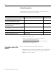
Related Documentation The table below provides a listing of publications that contain important information about using Compact I/O modules. For Read this document Document number A user manual containing information on how to install, MicroLogix 1500 User Manual use and program your MicroLogix 1500 controller. 1764-UM001 A user manual containing information on how to install, DeviceNet Adapter User Manual and use your 1769-ADN DeviceNet adapter.
Chapter 1 Module Operation Overview This chapter contains information about the following.
Module Operation About the 1769-BOOLEAN Module The 1769-BOOLEAN module is a 24V dc combination input/output module. The module outputs can be either directly controlled from your program or independently controlled by the module using configured Boolean expressions. These Boolean expressions are simple, logical combinations of the module hardware input states and soft inputs controlled by your program.
Module Operation 11 Module Description 1 IN OUT 2a 0 1 2 0 2 1 3 5 BOOLEAN 1 Bus lever (with locking function) 2a Upper panel mounting tab 2b Lower panel mounting tab 3 Module status LED 4 Module door with terminal identification label 5a Movable bus connector with female pins 5b Stationary bus connector with male pins 6 Nameplate label 7a Upper tongue-and-groove slots 7b Lower tongue-and-groove slots 8a Upper DIN rail latch 8b Lower DIN rail latch 9 Write-on label (user
Module Operation Boolean Expressions An expression is any legal combination of symbols that represents a value. An expression that results in a value of either TRUE or FALSE is called a Boolean expression. Every Boolean expression (except a null expression) consists of at least one operand and can have one or more operators. Operands are values, whereas operators are symbols that represent particular logical actions.
Module Operation 1769-BOOLEAN Module Block Diagram 13 The following figure is the block diagram for the 1769-BOOLEAN module.
Module Operation Wire the 1769-BOOLEAN Module Each terminal accepts as many as two wires with these restrictions. Wire Type Wire Size Terminal Screw Torque Retaining Screw Torque Solid Cu-90 °C (194 °F) 2.08…0.34 mm2 (14…22 AWG) 0.68 Nm (6 lb-in) 0.46 Nm (4.1 lb-in) Stranded Cu-90 °C (194 °F) 1.31…0.34 mm2 (16…22 AWG) 0.68 Nm (6 lb-in) 0.46 Nm (4.1 lb-in) Input and Output Circuit Diagrams The following figures illustrate the simplified input and output circuits.
Module Operation Control Outputs Using Boolean Expressions 15 You can configure the 1769-BOOLEAN module outputs to be controlled by Boolean expression (Boolean control mode). Format of Boolean Expression Each output is controlled with a separate expression. The fixed format of each Boolean expression is assumed to be of the form: Output State = (A x B) y C where A, B, and C are operands and x and y are logical operators you select.
Module Operation Variations of Boolean Expressions Variation Description Null All operands and operators assigned a value of “None”. A Only the first operand assigned a non-default value, all other operands and all operators assigned a value of “None”.
Module Operation 17 Output Delay When configured for Boolean control, the module's outputs are directed ON when the Boolean expression for each output channel is TRUE. The module can be configured to add a delay between an output's Boolean expression becoming TRUE and the output being placed into the ON state. The length of this delay time for an output operating in Boolean control mode can be configured to be between 0 (default) and 1 second in 1 ms increments.
Module Operation Output Delay and Duration Operation Since an output's Boolean expression can change in real time, configuring a delay and/or duration time when an output is in Boolean control mode could cause confusion. The module shall operate in the following manner when output delay and/or duration times are configured to non-default values (while an output is configured for Boolean control).
Module Operation 19 • In Case 2 the output will follow the state of the Boolean expression as long as the configured delay time has expired and the Boolean expression has maintained a TRUE state. When an output's Boolean expression transitions from FALSE to TRUE, the output will be turned ON only if the Boolean expression has maintained a state of TRUE for the entire length of the delay time.
Module Operation Publication 1769-RM016A-EN-P - July 2006
Module Operation 21 Example 2: Duration > 0, Delay < TRUE Time In this example, the output is configured with a duration time greater than 0, a delay time greater than 0, and the configured delay time is shorter than the time that the Boolean expression remains TRUE. Again, since the configured duration time is greater than 0, a “One-shot” pulse occurs on the output. The pulse starts an amount of time after the FALSE to TRUE transition of the Boolean expression equal to the configured delay time.
Module Operation Example 3: Duration > 0, Delay < TRUE Time, Retriggering Ignored In this example, the output is configured with a duration time greater than 0, a delay time greater than 0, and multiple transitions of the Boolean expression occur before the initial “One-shot” pulse duration is completed. The first FALSE to TRUE transition of the Boolean expression causes a “One-shot” pulse to occur.
Module Operation 23 Example 4: Duration > 0, Delay = 0, Duration > TRUE Time In this example, the output is configured with a duration time greater than 0, a delay time equal to 0, and the configured duration time is longer than the time that the Boolean expression remains TRUE. Since the configured duration time is greater than 0, a “One-shot” pulse occurs on the output.
Module Operation Example 5: Duration > 0, Delay = 0, Duration < TRUE Time In this example, the output is configured with a duration time greater than 0, a delay time equal to 0, and the configured duration time is shorter than the time that the Boolean expression remains TRUE. Again, since the configured duration time is greater than 0, a “One-shot” pulse occurs on the output.
Module Operation 25 Example 6: Duration = 0, Delay < TRUE Time In this example, the output is configured with a duration time equal to 0 (the output will remain ON only if the Boolean expression remains TRUE), a delay time greater than 0, and the Boolean expression continuously remains TRUE for a length of time greater than the configured delay time.
Module Operation Example 7: Duration = 0, Delay > TRUE Time In this example, the output is configured with a duration time equal to 0 (the output will remain ON only if the Boolean expression remains TRUE) and a delay time greater than 0. Conditions where the Boolean expression remains TRUE both for less than and longer than the configured delay time are illustrated.
Chapter 2 Installation and Wiring Overview This chapter tells you how to: • • • • • determine the power requirements for the module. avoid electrostatic damage. install the module. wire the module’s terminal block. wire input devices. • wire output devices.
Installation and Wiring Low Voltage Directive This product is tested to meet Council Directive 73/23/EEC Low Voltage, by applying the safety requirements of EN 61131-2 Programmable Controllers, Part 2 – Equipment Requirements and Tests. For specific information required by EN61131-2, see the appropriate sections in this publication, as well as the following Allen-Bradley publications: • Industrial Automation Wiring and Grounding Guidelines for Noise Immunity, publication 1770-4.
Installation and Wiring 29 Hazardous Location Considerations This equipment is suitable for use in Class I, Division 2, Groups A, B, C, D or nonhazardous locations only. The following attention statement applies to use in hazardous locations. ATTENTION Explosion Hazard • Substitution of components may impair suitability for Class I, Division 2. • Do not replace components or disconnect equipment unless power has been switched off or the area is known to be nonhazardous.
Installation and Wiring Remove Power ATTENTION Remove power before removing or inserting this module. When you remove or insert a module with power applied, an electrical arc may occur. An electrical arc can cause personal injury or property damage by: • sending an erroneous signal to your system’s field devices, causing unintended machine motion. • causing an explosion in a hazardous environment.
Installation and Wiring System Assembly 31 The module can be attached to the controller or an adjacent I/O module before or after mounting. Refer to Panel Mounting Using the Dimensional Template on page 33, for mounting instructions, or to DIN Rail Mount on page 34. Refer to Replace a Single Module Within a System on page 34, for information on working with a system that is already mounted. 3 4 2 1 6 1 5 1. Disconnect power. 2.
Installation and Wiring 6. Move the bus lever fully to the left (4) until it clicks, making sure it is locked firmly in place, to allow communication between the controller and module. ATTENTION When attaching I/O modules, it is very important that the bus connectors are securely locked together to be sure of proper electrical connection. 7. Attach an end cap terminator (5) to the last module in the system by using the tongue-and-groove slots as before. 8. Lock the end cap bus terminator (6).
Installation and Wiring 33 Panel Mount Mount the module to a panel using two screws per module. Use M4 or #8 panhead screws. Mounting screws are required on every module. Panel Mounting Using the Dimensional Template Overall hole spacing tolerance: ±0.4 mm (0.016 in.). Locate holes every 17.5 mm (0.689 in.) to allow for a mix of single-wide and one-and-a-half-wide modules (for example, the 1769-OA16 module). Host Controller Spacing for single-wide modules 35 mm (1.378 in.).
Installation and Wiring DIN Rail Mount The module can be mounted using the following DIN rails: 35 x 7.5 mm (EN 50 022 - 35 x 7.5) or 35 x 15 mm (EN 50 022 - 35 x 15). Before mounting the module on a DIN rail, close the DIN rail latches. Press the DIN rail mounting area of the module against the DIN rail. The latches will momentarily open and lock into place. Replace a Single Module Within a System The module can be replaced while the system is mounted to a panel (or DIN rail).
Installation and Wiring 35 6. Make sure that the bus lever, on the module to be installed and the right-side adjacent module, are in the unlocked (fully right position) before installing the replacement module. 7. Slide the replacement module into the open slot. 8. Connect the modules together by locking (fully left) the bus levers on the replacement module and the right-side adjacent module. 9. Replace the mounting screws (or snap the module onto the DIN rail).
Installation and Wiring System Wiring Guidelines Consider the following when wiring your system. General Guidelines • Input and output channels are isolated from each other. • Do not use the module’s NC terminals as connection points. Label the Terminals A removable, write-on label is provided with the module. Remove the label from the door, mark the identification of each terminal with permanent ink, and slide the label back into the door.
Installation and Wiring 37 Remove the Finger-safe Terminal Block When wiring field devices to the module, it is not necessary to remove the terminal block. If you remove the terminal block, use the write-on label on the side of the terminal block to identify the module slot location and type. RTB position can be indicated by circling either the R for right side or L for left side.
Installation and Wiring 3. Route the wire under the terminal pressure plate. You can use the bare wire or a spade lug. The terminals accept a 6.35 mm (0.25 in.) spade lug. TIP The terminal screws are non-captive. Therefore, it is possible to use a ring lug (maximum 1/4 in. o.d. with a 0.139 in. minimum i.d. (M3.5)) with the module. 4. Tighten the terminal screw making sure the pressure plate secures the wire. Recommended torque when tightening terminal screws is 0.68 Nm (6 lb-in).
Installation and Wiring 39 Input and Output Wiring This illustration describes the 1769-BOOLEAN module terminal layout. 1769-BOOLEAN Module Terminal Layout DANGER +VDC Do Not Remove RTB Under Power Unless Area is Nonhazardous OUT 0 OUT 1 OUT 2 OUT 3 OUT DC C OM N.C. N.C. N.C. IN 0 IN 1 IN 2 OUT 0 OUT 2 OUT DC COM N.C. IN 0 IN 3 IN 2 IN 5 IN 4 IN 7 IN 6 IN 4 IN 6 IN DC COM IN DC COM +VDC OUT 1 OUT 3 N.C. N.C.
Installation and Wiring Notes: Publication 1769-RM016A-EN-P - July 2006
Chapter 3 Module Data, Status, and Configuration Overview This chapter examines the module's data tables and channel configuration words. Topic Page 1769-BOOLEAN Module Addressing 42 1769-BOOLEAN Module Input Data File 44 1769-BOOLEAN Module Output Data File 44 1769-BOOLEAN Module Configuration Data File 46 Module Inputs The 1769-BOOLEAN module has eight, single-ended, 24V dc sinking inputs. Sinking describes the current flow between the I/O module and the field device.
Module Data, Status, and Configuration 1769-BOOLEAN Module Addressing Slot e Input Image File Slot e Output Image File Slot e Configuration File Publication 1769-RM016A-EN-P - July 2006 The 1769-BOOLEAN module memory map shows the input, output, and configuration files for the module.
Module Data, Status, and Configuration 43 1769-BOOLEAN Module Input Image The 1769-BOOLEAN module input image file represents real input data states and output state data echo. Input word 0 contains the state of the module's real inputs IN 0 through IN 7 in bits 0…7. Input word 1 contains the directed state of the module's outputs OUT0 through OUT3 in bits 0…3. These output data echo bits indicate the state of the module's output control circuits and do not represent the actual state of the outputs.
Module Data, Status, and Configuration The input data file lets you access module input read data for use in the control program, via word or bit access. The data file structure is shown in the table below. For each module, word 0, bits 0…7 in the input data file contain the values of the real inputs. For each module, word 1, bits 0…3 in the input data file contain the state of the module's output control circuits.
Module Data, Status, and Configuration 45 Virtual Inputs The control program determines eight virtual inputs. The module's outputs can be controlled by the module itself when the outputs are configured to use Boolean Control mode. Refer to Output Control (DB) on page 51, for information on configuring the module's outputs for Boolean Control mode.
Module Data, Status, and Configuration The configuration file determines how the module will operate. Parameters such as input filtering, output control mode, and Boolean expressions are set up using this file. This data file is readable and writable. The default value of the configuration file is all 0's.
Module Data, Status, and Configuration 47 Shaded bits must be set to 0. Default is all data file bits = 0. IMPORTANT The configuration file is typically modified using the programming software configuration screen. For information on how to configure the module using.
Module Data, Status, and Configuration Input Interrupts The module will support 8 input interrupts - one each for the 8 real inputs (IN 0 to IN 7). Interrupts are not supported by all controllers. Refer to your controller's user manual to determine if interrupts from expansion I/O modules are supported. Each real input can have one of 2 types of interrupts selected by the user.
Module Data, Status, and Configuration 49 Program State This configuration selection provides the individual selection for the control of the module outputs when the system enters the program mode. Word 3, bits 0…3 are used to select the program state control mode for module outputs OUT0 through OUT3.
Module Data, Status, and Configuration Fault State This configuration selection provides the individual selection for the control of the module outputs when the system enters the fault mode. Word 5, bits 0…3 are used to select the program state control mode for module outputs OUT0 through OUT3.
Module Data, Status, and Configuration 51 Output Control (DB) The outputs on the 1769-BOOLEAN module can be configured for two modes of control: direct control mode or Boolean Control mode. Each output is independently configured by use of the Disable Boolean (DB) control bits. Word 8, bit 0 determines the output control mode for OUT0. The output control modes for OUT1, OUT2, and OUT3 are determined similarly by bit 0 of words 16, 24, and 32.
Module Data, Status, and Configuration The type of interrupt is selected for OUT0 by configuring the IT_O bits (bits 4 and 5) of word 8. The output interrupt types for OUT1, OUT2, and OUT3 are similarly configured using the IT_O bits of words 16, 24, and 32. The type of interrupt is selected for each output by configuring the IT_O bits as follows.
Module Data, Status, and Configuration 53 The following table shows the bits patterns to use to configure the operands.
Module Data, Status, and Configuration Operators The operators that are used in each output's Boolean expression are selected from one of four possibilities. Each operator can be configured as one of the supported logic functions (AND, OR, or XOR) or can be configured as none (the operator is not used in the Boolean expression). Each output's Boolean expression operators are configured using one word in the configuration data file.
Module Data, Status, and Configuration 55 Each operator will perform the corresponding logical operation on the two operands it is between as illustrated in the following truth tables. OUT = A OR B A B OUT 0 0 0 0 1 1 1 0 1 1 1 1 OUT = A AND B A B OUT 0 0 0 0 1 0 1 0 0 1 1 1 OUT = A XOR B A B OUT 0 0 0 0 1 1 1 0 1 1 1 0 Output Delay When operating in Boolean Control mode, the module's outputs are directed ON when the Boolean expression for each output is TRUE.
Module Data, Status, and Configuration Each output's delay time is configured using one word in the configuration data file. For OUT0, output delay is configured using bits 0-9 of word 13. Configure the output delay for OUT1 with word 21; for OUT2 use word 29; and, for OUT3 use word 37. The following table shows the bits patterns to use to configure output delay time.
Module Data, Status, and Configuration 57 Each output's duration time is configured using one word in the configuration data file. For OUT0, output duration is configured using bits 0…9 of word 14. Configure the output duration for OUT1 with word 22; for OUT2 use word 30 and, for OUT3 use word 38. The following table shows the bits patterns to use to configure output duration time.
Module Data, Status, and Configuration Notes: Publication 1769-RM016A-EN-P - July 2006
Chapter 4 Module Diagnostics and Troubleshooting Overview This chapter describes troubleshooting the 1769-BOOLEAN module. This chapter contains information on: • safety considerations when troubleshooting. • the module's diagnostic features. • and module error condition data.
Module Diagnostics and Troubleshooting Program Alteration There are several possible causes of alteration to the user program, including extreme environmental conditions, Electromagnetic Interference (EMI), improper grounding, improper wiring connections, and unauthorized tampering. If you suspect a program has been altered, check it against a previously saved program on an EEPROM or UVPROM memory module.
Module Diagnostics and Troubleshooting 61 Module Error Types Error Type Module Error Field Value Bits 11…09 (Bin) Description No Errors 000 No error is present. The extended error field holds no additional information. Hardware Errors 001 General and specific hardware error codes are specified in the extended error information field. Configurat ion Errors 010 Module-specific error codes are indicated in the extended error field.
Module Diagnostics and Troubleshooting Error Codes Error codes can help troubleshoot your module.
Module Diagnostics and Troubleshooting Error Type Hex Equivalent (2) Module Extended Error Error Code Information Code 63 Error Description Binary Binary X409 010 0 0000 1001 Invalid Operand_B, OUT 0(4) X40A 010 0 0000 1010 Invalid Operand_B, OUT 1(4) X40B 010 0 0000 1011 Invalid Operand_B, OUT 2(4) X40C 010 0 0000 1100 Invalid Operand_B, OUT 3(4) X40D 010 0 0000 1101 Invalid Operand_C OUT 0(4) X40E 010 0 0000 1110 Invalid Operand_C, OUT 1(4) X40F 010 0 0000 1111 Invalid O
Module Diagnostics and Troubleshooting Module Inhibit Function CompactLogix controllers support the module inhibit function. See your controller manual for details. Whenever the 1769-BOOLEAN module is inhibited, the module's output state enters either the program state or the off state and the module's outputs are changed accordingly.
Appendix A 1769-BOOLEAN Module Specifications Compact Combination 24V dc Sink Input/Source Output BOOLEAN Control Module 1769-BOOLEAN General Specifications Attribute Value Closed Loop Time (Digital Filter = 0) Output on-state current > 5 mA: 100 µs max Output on-state current < 5 mA: 150 µs max Bus Current Draw, Max 220 mA at 5V dc Heat Dissipation 3.55 Total Watts (The Watts per point, plus the minimum Watts, with all points energized.
1769-BOOLEAN Module Specifications Attribute Value Nominal Impedance 2.0 kohm @ 24V dc 2.3 kohm @ 30V dc IEC Input Compatibility Type 3 Input Point to Bus (CompactBus) Isolation Verified by one of the following dielectric tests: 1200V ac for 1 s or 1697V dc for 1 s 75V dc working voltage (IEC Class 2 reinforced insulation) (1) Publication 1769-RM016A-EN-P - July 2006 Sinking Input - Sink describes the current flow between the I/O module and the field device.
1769-BOOLEAN Module Specifications 67 Output Specifications Attribute Value Voltage Category 24V dc Operating Voltage Range 20.4…26.4V dc (source(3)) Number of Outputs 4 Signal Delay, Max (resistive load) Turn-on: 10 µs, output on-state current > 5 mA Turn-off: 10 µs, output on-state current > 5 mA Off-state Leakage, Max(1) 1.0 mA @ 26.4V dc On-state Current, Min 1.0 mA On-state Voltage Drop, Max 1.0V dc @ 1.0 A Continuous Current per Point, Max 0.5 A @ 60 °C (140 °F) 1.
1769-BOOLEAN Module Specifications Certifications Certification Value Agency Certification C-UL UL CE Under CSA C22.2 No. 142 508 listed Compliant for all applicable directives Hazardous Environment Class Temperature Derating Class I, Division 2, Hazardous Location, Groups A, B, C, D (UL 1604, C-UL under CSA C22.2 No. 213) The area within the curve represents the safe operating range for the module under various conditions of user-supplied voltages and ambient temperatures.
1769-BOOLEAN Module Specifications Transistor Output Transient Pulses 69 The maximum duration of the transient pulse occurs when minimum load is connected to the output. However, for most applications, the energy of the transient pulse is not sufficient to energize the load. ATTENTION A transient pulse occurs in transistor outputs when the external dc supply voltage is applied to the output common terminals, for example, via the master control relay.
1769-BOOLEAN Module Specifications Notes: Publication 1769-RM016A-EN-P - July 2006
Appendix B Module Addressing and Configuration with MicroLogix 1500 Overview 71 This appendix examines the 1769-BOOLEAN module's addressing scheme and describes module configuration using MicroLogix 1500 and RSLogix 500 software.
Module Addressing and Configuration with MicroLogix 1500 Module Addressing This example shows the 1769-BOOLEAN module memory map.
Module Addressing and Configuration with MicroLogix 1500 73 Input Image The module's input image file represents input states and output data echo states. Input word 0 holds the input data that represents the value of inputs IN0 to IN7. Input word 1 represents the directed state of the module's outputs OUT0 through OUT3. For example, to obtain the state of input IN2 of the module when it is in slot 3, use address I:3.0/2. Word Slot Bit I:3.
Module Addressing and Configuration with MicroLogix 1500 Output Image The module's output image file represents directed output states and virtual input states. Output word 0 holds the directed states for the module's outputs (OUT0 through OUT3) when any of the outputs are configured for direct control mode. Output word 1 holds the states of the module's virtual inputs (V0 through V7) can be used as Boolean operands when any of the module's outputs are configured for Boolean Control mode.
Module Addressing and Configuration with MicroLogix 1500 75 Configuration File The configuration file contains information that you use to define how the module operates. Refer to Module Data, Status, and Configuration on page 41, for more configuration information. The configuration file is modified using the programming software configuration screen. Refer to Configure the 1769-BOOLEAN Module in a MicroLogix 1500 System on page 76 for an example of module configuration using RSLogix 500 software.
Module Addressing and Configuration with MicroLogix 1500 Configure the 1769-BOOLEAN Module in a MicroLogix 1500 System This example takes you through configuring your 1769-BOOLEAN module with RSLogix 500 programming software. This application example assumes your module is installed as expansion I/O in a MicroLogix 1500 system that RSLinx software is properly configured, and a communications link has been established between the MicroLogix controller and RSLogix 500 software.
Module Addressing and Configuration with MicroLogix 1500 77 4. Enter your configuration data. Refer to 1769-BOOLEAN Module Configuration Data File on page 46 for more information on configuration data word and bit assignments. 5. Click OK.
Module Addressing and Configuration with MicroLogix 1500 Notes: Publication 1769-RM016A-EN-P - July 2006
Appendix C Configuration Using the RSLogix 5000 Generic Profile for CompactLogix Controllers Overview This appendix describes how to configure the 1769-BOOLEAN module for a CompactLogix controller. Configure the Module To configure a 1769-BOOLEAN module for a CompactLogix controller in RSLogix 5000 software using the Generic Profile, you must first begin a new project in RSLogix 5000 software. 1. Click the new project icon or on the FILE pull-down menu and select New. 2. Choose your controller type.
Configuration Using the RSLogix 5000 Generic Profile for CompactLogix Controllers The main RSLogix 5000 screen appears. The last entry in the controller organizer on the left of the screen is a line labeled [0] CompactBus Local. 5. Right-click this line and select New Module. The Select Module screen appears. This screen narrows your search for I/O modules to configure into your system.
Configuration Using the RSLogix 5000 Generic Profile for CompactLogix Controllers 81 6. Expand the + next to Other to use the 1769 generic selection for the 1769-BOOLEAN module. 7. Click OK. The New Module default Generic Profile screen appears. This is the default Generic Profile screen. 8. (optional) Fill in the Generic Profile screen name. This helps to easily identify the module type configured on your local Compact Bus.
Configuration Using the RSLogix 5000 Generic Profile for CompactLogix Controllers 11. Enter the Comm Format, Assembly Instance numbers and their associated sizes into the Generic Profile and click OK. The Module Properties screen appears. 12. (optional) Check the Inhibit Module checkbox. The default for this parameter is not to inhibit the module. 13. (optional) Check the Major Fault on Controller checkbox.
Configuration Using the RSLogix 5000 Generic Profile for CompactLogix Controllers Configure I/O Modules 83 Once you have created generic profiles for each 1769-BOOLEAN module in your system, you must then enter configuration information into the Tag database that has been automatically created from the generic profile information you entered for each of these modules. This configuration information is downloaded to each module at program download, going to run, and at power cycle.
Configuration Using the RSLogix 5000 Generic Profile for CompactLogix Controllers Tag addresses are automatically created for configured I/O modules. All local I/O addresses are preceded by the word Local. These addresses have the following format: • Input Data: Local:s.I • Output Data: Local:s.O • Configuration Data: Local:s.C where s is the slot number assigned the I/O modules in the Generic Profiles.
Appendix D Configure Modules in a Remote DeviceNet System with a 1769-ADN DeviceNet Adapter Overview In this example, the 1769-BOOLEAN module is in a remote DeviceNet system controlled by a 1769-ADN DeviceNet adapter. RSNetWorx for DeviceNet software, version 2.23 or later, is used to configure the network and the I/O modules.
Configure Modules in a Remote DeviceNet System with a 1769-ADN DeviceNet Adapter Add the DeviceNet Adapter to the Scanlist In this part of the example, the 1769-ADN adapter is added to the DeviceNet scanner’s scanlist. 1. Start the RSNetWorx for DeviceNet software. 2. In the left column under Category, click the + sign next to Communication Adapters. 3. In the list of products, double-click the 1769-ADN to place it on the network.
Configure Modules in a Remote DeviceNet System with a 1769-ADN DeviceNet Adapter 87 4. To configure I/O for the adapter, double-click the adapter icon that appears on the network. 5. Click the Module Configuration tab. TIP The I/O Summary tab provides the configured size and format of the I/O data. The Transaction tab lets you send services supported by the device. The Clear/Reset Memory transaction returns the module’s configuration to the factory defaults, that is, empty.
Configure Modules in a Remote DeviceNet System with a 1769-ADN DeviceNet Adapter Configure the 1769-BOOLEAN Module Example The 1769-ADN adapter appears in slot 0. Your I/O modules, power supplies, end caps, and interconnect cables must be entered in the proper order, following the 1769 I/O rules contained in the DeviceNet Adapter User Manual, publication 1769-UM001. To simplify this example, we placed the module in slot 1 to show how it is configured. 1.
Configure Modules in a Remote DeviceNet System with a 1769-ADN DeviceNet Adapter 89 3. Double-click on the module. 4. Under the General tab, select the appropriate bank. Bank 1 was selected in this example.
Configure Modules in a Remote DeviceNet System with a 1769-ADN DeviceNet Adapter 5. Under the Configuration Settings tab, you can select the parameter that you want to configure and initiate an action using the toolbar. 6. Set each parameter's current value to match the desired 1769-BOOLEAN module configuration settings. 7. Click OK or Cancel to exit this screen and return to the Configuration screen. The revision number for the 1769-BOOLEAN module is one.
How Are We Doing? Your comments on our technical publications will help us serve you better in the future. Thank you for taking the time to provide us feedback. You can complete this form and mail (or fax) it back to us or email us at RADocumentComments@ra.rockwell.com Pub. Title/Type Compact Combination 24V dc Sink Input/Source Output BOOLEAN Control Module Cat. No. 1769-BOOLEAN Pub. No. 1769-RM016A-EN-P Pub. Date July 2006 Part No. 953014-70 Please complete the sections below.
PLEASE FASTEN HERE (DO NOT STAPLE) PLEASE FOLD HERE NO POSTAGE NECESSARY IF MAILED IN THE UNITED STATES BUSINESS REPLY MAIL FIRST-CLASS MAIL PERMIT NO.
Index Numerics 1769-ADN 47, 48, 85 configuration example 85 user manual 8 1769-BOOLEAN configuration file 46 description 10 diagnostics 59 extended error codes 62 hardware features 11 inhibit function 64 max output amperes 68 module addressing 42 module block diagram 13 module configuration file 43 module input image 43 module memory map 72 module output image 43 module terminal layout 39 specifications 65 troublehooting 59 wiring 14 1769-ECL 32 1769-ECR 32 B bits patterns used to configure the operands 53
Index grounding 35 heat and noise considerations 30 internal diagnostic tests 60 interrupt event 48, 52 L Low Voltage Directive 28 M MicroLogix 1500 47, 48 module addressing and configuration 71 module addressing 42 certifications 68 configuration 11 configuration errors 61 configuration file 43, 46 data, status, and configuration 41 description 11 diagnostics 59 DIN rail mount 33 direct control of outputs 44 error codes 61, 62 error definitions 60 error field 60 error types 61 extended error informa
Rockwell Automation Support Rockwell Automation provides technical information on the Web to assist you in using its products. At http://support.rockwellautomation.com, you can find technical manuals, a knowledge base of FAQs, technical and application notes, sample code and links to software service packs, and a MySupport feature that you can customize to make the best use of these tools.
Compact Combination 24V dc Sink Input/Source Output BOOLEAN Control Module Reference Manual