Installation Instructions Compact Combination 24V dc Sink Input/Source Output BOOLEAN Control Module Catalog Number 1769-BOOLEAN Inside . . .
Important User Information Solid state equipment has operational characteristics differing from those of electromechanical equipment. Safety Guidelines for the Application, Installation and Maintenance of Solid State Controls (Publication SGI-1.1 available from your local Rockwell Automation sales office or online at http://rockwellautomation.com/literature) describes some important differences between solid state equipment and hard-wired electromechanical devices.
Prevent Electrostatic Discharge ATTENTION Electrostatic discharge can damage integrated circuits or semiconductors if you touch bus connector pins. Follow these guidelines when you handle the module: – – – – – – Touch a grounded object to discharge static potential. Wear an approved wrist-strap grounding device. Do not touch the bus connector or connector pins. Do not touch circuit components inside the module. If available, use a static-safe work station.
Hazardous Location Considerations This equipment is suitable for use in Class I, Division 2, Groups A, B, C, D or non-hazardous locations only. The following WARNING statement applies to use in hazardous locations. WARNING EXPLOSION HAZARD • Substitution of components may impair suitability for Class I, Division 2. • Do not replace components or disconnect equipment unless power is switched off or the area is known to be non-hazardous.
About the 1769-BOOLEAN Module Compact I/O is suitable for use in an industrial environment when installed in accordance with these instructions. Specifically, this equipment is intended for use in clean, dry environments (Pollution degree 2(1)) and to circuits not exceeding Over Voltage Category II(2) (IEC 60664-1)(3).
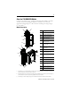
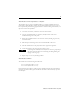
Install the 1769-BOOLEAN Module Attach the module to the controller or an adjacent I/O module before or after mounting. For mounting instructions, see Mount Module to Panel Using the Dimensional Template, or Mount Module to DIN Rail. To work with a system that is already mounted, see Replace a Single Module Within a System. The following procedure shows you how to assemble the Compact I/O system. 3 4 2 1 6 1 5 30536-M 1. Disconnect power. 2.
7. Attach an end-cap terminator (5) to the last module in the system by using the tongue-and-groove slots as before. 8. Lock the end-cap bus terminator (6). IMPORTANT You must use a 1769-ECR or 1769-ECL right or left end cap to terminate the end of the serial communication bus. Replace a Single Module Within a System The module can be replaced while the system is mounted to a panel (or DIN rail). 1. Remove power. Refer to Remove Power on page 3. 2.
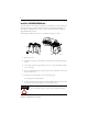
Mount Expansion I/O ATTENTION During panel or DIN rail mounting of all devices, be sure that all debris, that is, metal chips or wire strands, is kept from falling into the module. Debris that falls into the module could cause damage when cycling power. Minimum Spacing End Cap Compact I/O Compact I/O Compact I/O Compact I/O Controller Side Compact I/O Top Maintain spacing from enclosure walls, wireways, or adjacent equipment. Allow 50 mm (2 in.
Mount Module to Panel Using Modules as a Template This procedure lets you use the assembled modules as a template for drilling holes in the panel. Refer to Mount Module to Panel Using the Dimensional Template on page 8 if you have sophisticated panel-mounting equipment. Due to module-mounting hole tolerance, it is important to follow this procedure: 1. On a clean work surface, assemble no more than three modules. 2.
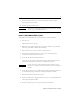
Wire the 1769-BOOLEAN Module Each terminal accepts as many as two wires with these restrictions: Wire Type Wire Size Terminal Screw Torque Retaining Screw Torque Solid Cu-90 °C (194 °F) 2.08…0.34 mm2 (14…22 AWG) 0.68 Nm (6 in-lb) 0.46 Nm (4.1 in-lb) Stranded Cu-90 °C (194 °F) 1.31…0.34 mm2 (16…22 AWG) 0.68 Nm (6 in-lb) 0.46 Nm (4.
Input/Output Wiring Ground the 1769-BOOLEAN Module This product is intended to be mounted to a well-grounded mounting surface such as a metal panel. Additional grounding connections from the module’s mounting tabs or DIN rail (if used) are not required unless the mounting surface cannot be grounded. Refer to Industrial Automation Wiring and Grounding Guidelines, Allen-Bradley publication 1770-4.1, for additional information.
Configure the 1769-BOOLEAN Module The following I/O memory mapping lets you configure the 1769-BOOLEAN module. Output Data File Word For each module, slot x, word 0 in the output data file contains the control program’s directed state of the module’s output points when operated in Direct Control mode. Direct Control mode is active when an output’s disable BOOLEAN (DB_x) bit is set in the configuration data file.
Configuration Data File The manipulation of bits from this file is normally done with programming software (for example, RSLogix 500 software or RSNetWorx for DeviceNet software) during initial configuration of the system. In that case, graphical screens provided by the programming software simplify configuration. Word Some systems, like the 1769-ADN DeviceNet adapter system, also allow the bits to be altered as part of the control program using communication rungs.
Word 14 Bit Position 15 14 13 12 11 10 9 8 7 6 5 4 3 20 Operator_ 2_1 21 Output Delay 1 22 Output Duration 1 2 1 0 Operator_ 1_1 23 24 IT_O2 EI_ O2 25 Operand_A_2 26 Operand_B_2 27 Operand_C_2 28 Operator_ 2_2 29 Output Delay 2 30 Output Duration 2 DB_ 1 Operator_ 1_2 31 32 IT_O3 EI_ O3 33 Operand_A_3 34 Operand_B_3 35 Operand_C_3 36 Operator_ 2_3 37 Output Delay 3 38 Output Duration 3 DB_ 3 Operator_ 1_3 39 Shaded bit positions must be set to 0.
IT_Ox: Output interrupt type. See page 16. Operand_A_x: BOOLEAN operand A. See page 17. Operand_B_x: BOOLEAN operand B. See page 17. Operand_C_x: BOOLEAN operand C. See page 17. Operator_1_x: BOOLEAN operator 1. See page 19. Operator_2_x: BOOLEAN operator 2. See page 19. Output delay x: Delay time from BOOLEAN expression transition from false to true until output directed to transition from off to on. See page 20. Output duration x: Pre-determined output pulse duration time.
Word Bit Position 15 14 13 12 11 10 Output Control (DB_x) Enable Output Interrupt 8, 16, 24, 32 Output Interrupt Type 9 8 7 6 5 4 3 2 1 0 Direct Control 1 BOOLEAN Control 0 Enable 1 Disable 0 BOOLEAN Expression FALSE to TRUE 0 0 Output Directed OFF to ON 0 1 BOOLEAN Expression TRUE to FALSE 1 0 Output Directed ON to OFF 1 1 Darker shaded bit positions must be set to 0.
Word Bit Position 15 14 13 12 11 10 None 9, 10, 11 17, 18, 19 25, 26, 27 33, 34, 35 9 8 7 6 5 4 3 2 1 0 0 0 0 0 0 0 Operand_ Real Input 0 A_0 Operand_ Inverted B_0 Real Operand_ Input 0 C_0 Real Input 1 0 0 0 0 0 1 0 0 0 0 1 0 0 0 0 0 1 1 Inverted Real Input 1 0 0 0 1 0 0 0 0 0 1 0 1 0 0 0 1 1 0 Real Input 3 0 0 0 1 1 1 Inverted Real Input 3 0 0 1 0 0 0 0 0 1 0 0 1 0 0 1 0 1 0 Real Input 5 0 0 1 0 1 1 Inverted R
Word Bit Position 15 14 13 12 11 10 5 4 3 2 1 0 Inverted Real Input 7 0 1 0 0 0 0 Virtual Input 0 0 1 0 0 0 1 Inverted Virtual Input 0 0 1 0 0 1 0 Virtual Input 1 0 1 0 0 1 1 Inverted Virtual Input 1 0 1 0 1 0 0 Virtual Input 2 0 1 0 1 0 1 Inverted Virtual Input 2 0 1 0 1 1 0 Virtual Input 3 0 1 0 1 1 1 Inverted Virtual Input 3 0 1 1 0 0 0 Virtual Input 4 0 1 1 0 0 1 Inverted Virtual Input 4 0 1 1 0 1 0 Virtual Input 5
Word Bit Position 15 14 13 12 11 10 9 8 7 6 Inverted Virtual Input 7 5 4 3 2 1 0 1 0 0 0 0 0 Shaded bit positions must be set to 0. Entering a binary value greater than 100000 (greater than 32 decimal) results in a configuration error.
Word Bit Position 13, 21, 29, 37 15 14 13 12 11 10 9 8 7 6 5 4 3 2 1 0 Output Delay 0 0 ms 0 0 0 0 0 0 0 0 0 0 1 ms 0 0 0 0 0 0 0 0 0 1 Output Delay 1 2 ms 0 0 0 0 0 0 0 0 1 0 3 ms 0 0 0 0 0 0 0 0 1 1 Output Delay 2 4 ms 0 0 0 0 0 0 0 1 0 0 5 ms 0 0 0 0 0 0 0 1 0 1 Output Delay 3 6 ms 0 0 0 0 0 0 0 1 1 0 7 ms 0 0 0 0 0 0 0 1 1 1 993 ms 1 1 1 1 1 0 0 0 0 1 994 ms 1 1 1 1 1 0 0 0 1
Word Bit Position 15 14 13 12 11 10 9 8 7 6 5 4 3 2 1 0 None Output Duration 0 1 ms 0 0 0 0 0 0 0 0 0 0 0 0 0 0 0 0 0 0 0 1 Output Duration 1 2 ms 0 0 0 0 0 0 0 0 1 0 3 ms 0 0 0 0 0 0 0 0 1 1 Output Duration 2 4 ms 0 0 0 0 0 0 0 1 0 0 5 ms 0 0 0 0 0 0 0 1 0 1 Output 6 ms 14, Duration 3 7 ms 22, ...
Specifications Compact I/O - 1769-BOOLEAN General Specifications Specification Value Closed Loop Time (Digital Filter = 0) Output on-state current > 5 mA: 100 µs max Output on-state current < 5 mA: 150 µs max Bus Current Draw, Max 220 mA at 5V dc Heat Dissipation 3.55 Total Watts (The Watts per point, plus the minimum Watts, with all points energized.) Power Supply Distance Rating 8 (The module may not be more than 8 modules away from the power supply or controller.
Input Specifications Off-state Current, Max 1.5 mA On-state Voltage, Min 10V dc On-state Current, Min 2.0 mA Inrush Current, Max 250 mA Nominal Impedance 2.0 kohm @ 24V dc 2.
(3) Sourcing Output - Source describes the current flow between the I/O module and the field device. Sourcing output circuits supply source current to sinking field devices. Field devices connected to the negative side (dc common) of the field power supply are sinking field devices. Europe: DC sinking input and sourcing output module circuits are the commonly used options.
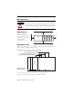
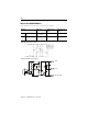
Temperature Derating The area within the curve represents the safe operating range for the module under various conditions of user-supplied voltages and ambient temperatures. Figure 1 1769-BOOLEAN Maximum Output Amperes per Module vs. Temperature Maximum Amperes per Module 3.8 3.6 3.4 3.2 3 2.8 2.6 2.4 2.2 2 25 30 35 40 45 50 55 60 65 o Ambient Temperature C Figure 2 1769-BOOLEAN Maximum Output Amperes per Point vs.
Transistor Output Transient Pulses The maximum duration of the transient pulse occurs when minimum load is connected to the output. However, for most applications, the energy of the transient pulse is not sufficient to energize the load. ATTENTION A transient pulse occurs in transistor outputs when the external dc supply voltage is applied to the output common terminals, for example, via the master control relay. The sudden application of voltage creates this transient pulse.
Additional Resources If you would like a manual, you can: • Download a free electronic version from www.ab.com/literature • Purchase a printed manual by contacting your local distributor or Rockwell Automation representative For Refer To This Document Pub. No.
Rockwell Automation Support Rockwell Automation provides technical information on the web to assist you in using its products. At http://support.rockwellautomation.com, you can find technical manuals, a knowledge base of FAQs, technical and application notes, sample code and links to software service packs, and a MySupport feature that you can customize to make the best use of these tools.