Installation Instructions Compact 1769-ASCII Module Cat. No. 1769-ASCII Inside… About the Module ............................................................................................4 Install the Module.............................................................................................5 Assemble the System........................................................................................6 Mount Expansion I/O .............................................................................
Compact 1769-ASCII Module Important User Information Because of the variety of uses for the products described in this publication, those responsible for the application and use of these products must satisfy themselves that all necessary steps have been taken to assure that each application and use meets all performance and safety requirements, including any applicable laws, regulations, codes and standards.
Compact 1769-ASCII Module 3 IMPORTANT ATTENTION Identifies information that is critical for successful application and understanding of the product. Environment and Enclosure This equipment is intended for use in a Pollution Degree 2 industrial environment, in overvoltage Category II applications (as defined in IEC publication 60664-1), at altitudes up to 2000 meters without derating. This equipment is considered Group 1, Class A industrial equipment according to IEC/CISPR Publication 11.
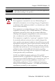
Compact 1769-ASCII Module About the Module The 1769-ASCII module provides a flexible network interface to a wide variety of RS-232, RS-485, and RS-422 ASCII devices. The module provides the communication connections to the ASCII device.
Compact 1769-ASCII Module 5 Install the Module Compact I/O is suitable for use in an industrial environment when installed in accordance with these instructions. Specifically, this equipment is intended for use in clean, dry environments (Pollution Degree 2(1)) and to circuits not exceeding Over Voltage Category II(2) (IEC 60664-1).(3) ATTENTION Preventing Electrostatic Discharge This equipment is sensitive to electrostatic discharge, which can cause internal damage and affect normal operation.
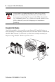
Compact 1769-ASCII Module ATTENTION This product is grounded through the DIN rail to chassis ground. Use zinc-plated, yellow-chromate steel DIN rail to assure proper grounding. The use of other DIN rail materials (e.g., aluminum, plastic, etc.), which can corrode, oxidize, or are poor conductors, can result in improper or intermittent grounding. Assemble the System Attach the module to the controller or an adjacent I/O module before or after mounting.
Compact 1769-ASCII Module 7 1. Disconnect power. ATTENTION Remove power before removing or inserting this module. When you remove or insert a module with power applied, an electrical arc may occur. An electrical arc can cause personal injury or property damage by: • sending an erroneous signal to your system’s field devices, causing unintended machine motion • causing an explosion in a hazardous environment Electrical arcing causes excessive wear to contacts on both the module and its mating connector.
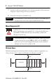
Compact 1769-ASCII Module 7. Attach an end-cap terminator (5) to the last module in the system by using the tongue-and-groove slots as before. 8. Lock the end-cap bus terminator (6). You must use a 1769-ECR or -ECL right- or left-end cap to terminate the end of the serial communication bus. IMPORTANT Mount Expansion I/O ATTENTION During panel or DIN rail mounting of all devices, be sure that all debris (metal chips, wire strands, etc.) is kept from falling into the module.
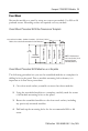
Compact 1769-ASCII Module 9 Panel Mount Mount the module to a panel by using two screws per module. Use M4 or #8 panhead screws. Mounting screws are required on every module. Panel Mount Procedure With the Dimensional Template Compact I/O Right End Cap 28.5 (1.12) 35 (1.38) Compact I/O 122.6±0.2 (4.826±0.008) Compact I/O 132 (5.197) Host Controller For more than 2 modules: (number of modules - 1) X 35 mm (1.38 in.) Refer to host controller documentation for this dimension.
Compact 1769-ASCII Module 5. Place the modules back on the panel, and check for proper hole alignment. 6. Attach the modules to the panel using the mounting screws. If mounting more modules, mount only the last one of this group and put the others aside. This reduces remounting time during drilling and tapping of the next group. 7. Repeat steps 1 to 6 for any remaining modules. Mount on the DIN Rail The module can be mounted on these DIN rails: • 35 x 7.5 mm (EN 50022 - 35 x 7.
Compact 1769-ASCII Module 11 Replace a Single Module Within a System The module can be replaced while the system is mounted to a panel or DIN rail. 1. Remove power. ATTENTION Remove power before removing or inserting this module. When you remove or insert a module with power applied, an electrical arc may occur.
Compact 1769-ASCII Module 6. Before installing the replacement module, be sure that the bus lever on the module to be installed and on the right-side adjacent module are in the unlocked (fully right) position. 7. Slide the replacement module into the open slot. 8. Connect the modules together by locking (fully left) the bus levers on the replacement module and the right-side adjacent module. 9. Replace the mounting screws (or snap the module onto the DIN rail).
Compact 1769-ASCII Module 13 Connect the D-sub Connector Pins All pins are active at all times. IMPORTANT Pins unused for a particular physical network must not be connected via the serial cable to any other device. In particular, do not use cables 1747-CP3 and 1756-CP3.
Compact 1769-ASCII Module Figure 1 RS-232 Wiring Diagram - Module to DTE Device (Hardware Handshaking Disabled) ASCII DTE DTE 1 NC DCD 2 RXD TXD 3 TXD RSD 4 NC DSR 5 COM COM 6 NC DTR 7 8 RTS CTS CTS RTS 9 NC GND(1) 9-pin 25-pin 1 3 2 6 5 4 8 7 8 2 3 6 7 20 5 4 1 (1) Connect to the shield of the cable.
Compact 1769-ASCII Module 15 Figure 3 RS-422 Wiring Diagram ASCII 1 TXD- 2 NC NC 3 4 RXD5 COM 6 RXD+ RXD- TXDCOM TXD+ 7 8 RTS CTS 9 TXD+ RXD+ Figure 4 RS-485 Wiring Diagram ASCII 1 TRXD2 NC 3 4 5 6 NC NC COM NC TRXD- COM 7 8 RTS CTS 9 TRXD+ TRXD+ Publication 1769-IN068B-EN-P - May 2005
Compact 1769-ASCII Module I/O Memory Mapping The 1769-ASCII module supports an input assembly that is accessible through the Assembly Object (Class 4), Instance 101. The input assembly is up to 108 words. The module supports an output assembly that is accessible through the Assembly Object (Class 4), Instance 100. The output assembly is up to 108 words. Alternate Mode (One Channel at a Time) Output File Word Maximum size is shown below.
Compact 1769-ASCII Module 17 • CNO = Channel number of the output data being sent. This bit is set by the PLC controller or other user program to tell the ASCII module which port’s data is being sent to the ASCII module. • Reserved bits should be set to 0. Alternate Mode (One Channel at a Time) Input File Word Maximum size is shown below. Refer to the Compact I/O 1769-ASCII Module User Manual, publication 1769-UM012, to use smaller input files.
Compact 1769-ASCII Module • NR = Non-delimited record. An input record is received and sent to the Compact bus interface that was not triggered by a delimiter character. This occurs when either the buffer is filled to its maximum receive size or a Message Timeout has occurred. • RF = Data in the receive FIFO. The FIFO is not empty. The input FIFO has not sent all of its data to the Compact bus interface. • TF = Data in transmit FIFO. The FIFO is not empty.
Compact 1769-ASCII Module 19 Simultaneous Mode (Two Channels) Input File Word Maximum size is shown below. Refer to the Compact I/O 1769-ASCII Module User Manual, publication 1769-UM012, to use smaller output files.
Compact 1769-ASCII Module • TS = Transmit sent. Indicates the ASCII module has sent the data indicated by the Tx Transaction ID and can accept more transmit data. • ND = New data. Only used for Handshake mode. • HE = Handshake error. Only used for Handshake mode. • NR = Non-delimited record. An input record is received and sent to the Compact bus interface that was not triggered by a delimiter character.
Compact 1769-ASCII Module 21 Simultaneous Mode (Two Channels) Output File Word Maximum size is shown below. Refer to the Compact I/O 1769-ASCII Module User Manual, publication 1769-UM012, to use smaller output files.
Compact 1769-ASCII Module Configuration File Word The 1769-ASCII module supports a configuration assembly that is accessible through the Assembly Object (Class 4), Instance 102. The configuration assembly is 31 words. The addresses assume a 16-bit data structure where all 16-bit values are INT(1). The least significant word occupies the smaller byte addresses.
Word Compact 1769-ASCII Module 23 Description Values Valid Data Values Module Production Data 8 Pad Character(1) 0…127/255 0…0x7f (0…127) for 7-bit data 0…0xff (0…255) for 8-bit data 9 Receive Swap Mode 0…2 0 = disabled, 1 = 16-bit, 2 = 32-bit 10 Master Handshake Mode 0…1 0 = master/slave handshake, 1 = produce immediate 11 Message Time Out 0…65535 0 = none, 1 to 65535 ms 12 Max Number of Transmit Characters 0…200 In Simultaneous mode, the total number of channel 0 characters plus channel
Word 24 Compact 1769-ASCII Module Description Values Valid Data Values 18 Max Number of Receive Characters 0…200 In Simultaneous mode, the total number of channel 0 characters plus channel 1 characters cannot exceed 200.
Compact 1769-ASCII Module 25 Configure the 1769-ASCII Module Enter the configuration data for your 1769-ASCII application into RSLogix 500 software or RSLogix 5000 software. If your message sizes differ from the default, change the size of the input and output connection parameters. Configure with RSLogix 500 Software RSLogix 500, version 7, will include a 1769-ASCII profile. If you use a previous version, follow this procedure to configure your module. 1.
Compact 1769-ASCII Module 2. Enter the appropriate values as listed below. 3. Choose OK. 4. From the Generic Extra Data Config tab, enter your configuration data. Refer to Configuration File on page 22.
Compact 1769-ASCII Module 27 Configure with RSLogix 5000 Software 1. Right-click on the 1769-ASCII module and choose Properties. Use the default Assembly Instance numbers. 2. Enter the name of your module in the Name field. 3. Enter the connection parameters according to your controller. Controller 1769-L31, -L32C, -L32E, -L35CR, -L35E (1) Maximum size listed. (2) The created tag will be 198 INTs long. Input Output Configuration Size(1) Size(1) Size(2) 108 108 31 4. Choose OK.
Compact 1769-ASCII Module 5. Double-click on the controller tags. 6. Enter your configuration data. Refer to Configuration File on page 22. For this example, we entered the Serial Character Framing from Word 1.
Compact 1769-ASCII Module 29 Specifications Vendor I.D.
Compact 1769-ASCII Module General Specifications Environmental Conditions Operational Temperature IEC 60068-2-1 (Test Ad, Operating Cold), IEC 60068-2-2 (Test Bd, Operating Dry Heat), IEC 60068-2-14 (Test Nb, Operating Thermal Shock): 0…60 °C (32…140 °F) Storage Temperature IEC 60068-2-1 (Test Ab, Unpackaged Non-operating Cold), IEC 60068-2-2 (Test Bb, Unpackaged Non-operating Dry Heat), IEC 60068-2-14 (Test Na, Unpackaged Non-operating Thermal Shock): -40…85 °C (-40…185 °F) Relative Humidity IEC 60
Compact 1769-ASCII Module 31 Conducted RF Immunity IEC 61000-4-6: 10 Vrms with 1 kHz sine-wave 80% AM from 150 kHz…80 MHz Enclosure Type Rating None (open-style) Dimensions (HxWxL), Imperial 3.39 x 1.33 x 4.60 in Dimensions (HxWxL), Metric 87 x 34 x 118 mm Serial Port Connectors Two DB-9 male (with pins) Conductors Category 21 Weight, Imperial 0.4 lb Weight, Metric 0.
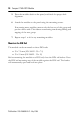
Compact 1769-ASCII Module Status Indicators The following table defines the ASCII module status indicators. Status Indicator State Meaning OK Off No power, module is not configured, or no bus master Solid green In run mode. The led will blink red once during powerup.
Compact 1769-ASCII Module 33 Troubleshoot with Error Codes Value (Hex) Meaning 0 No error 200…3FF Hardware error 400…5FF Configuration error 800…DFF Reserved for future use E00…FFF Bus master detected error Configuration Error Codes Value (Hex) Meaning Description Global Module Errors 0 No error The 1769-ASCII module adds no module-specific errors. 401 Max output array size exceeded The maximum output array size is too large.
Compact 1769-ASCII Module Value (Hex) Meaning Description Channel 0 Module Errors 430 Data buffer mode 0 = alternate mode; 1 = simultaneous mode. Anything else is invalid. 440 Invalid serial port framing The serial port framing specified is invalid. 441 Invalid serial port speed The serial port speed specified is invalid. 442 Invalid max number of receive characters The maximum number of receive characters specified for channel 0 is too large.
Compact 1769-ASCII Module 35 Value (Hex) Meaning Description 44E Invalid transmit swap mode The transmit swap mode specified is invalid. 44F-77F Undefined channel 0 error An undefined error has occurred. Channel 1 Module Errors 480 Invalid serial port framing The serial port framing specified is invalid. 481 Invalid serial port speed The serial port speed specified is invalid.
Compact 1769-ASCII Module Value (Hex) Meaning Description 48C Invalid transmit record end mode The transmit record end mode specified is invalid. 48D Invalid transmit end delimiter The transmit end delimiter specified is invalid. 48E Invalid transmit swap mode The transmit swap mode specified is invalid.
Compact 1769-ASCII Module 37 North American Hazardous Location Approval The following information applies when operating this equipment in hazardous locations: Informations sur l'utilisation de cet équipement en environnements dangereux: Products marked “CL I, DIV 2, GP A, B, C, D” are suitable for use in Class I Division 2 Groups A, B, C, D, Hazardous Locations and nonhazardous locations only.
Compact 1769-ASCII Module WARNING EXPLOSION HAZARD AVERTISSEMENT RISQUE D'EXPLOSION Do not disconnect equipment unless power has been removed or the area is known to be nonhazardous. Couper le courant ou s'assurer que l'environnement est classé non dangereux avant de débrancher l'équipement. Do not disconnect connections to this equipment unless power has been removed or the area is known to be nonhazardous.
Compact 1769-ASCII Module 39 Notes: Publication 1769-IN068B-EN-P - May 2005
Rockwell Automation Support Rockwell Automation provides technical information on the web to assist you in using its products. At http://support.rockwellautomation.com, you can find technical manuals, a knowledge base of FAQs, technical and application notes, sample code and links to software service packs, and a MySupport feature that you can customize to make the best use of these tools.