User Manual Compact I/O ASCII Module Catalog Numbers 1769-ASCII
Important User Information Read this document and the documents listed in the additional resources section about installation, configuration, and operation of this equipment before you install, configure, operate, or maintain this product. Users are required to familiarize themselves with installation and wiring instructions in addition to requirements of all applicable codes, laws, and standards.
Summary of Changes This manual contains new and updated information. Changes throughout this revision are marked by change bars, as shown to the right of this paragraph. New and Updated Information This table contains the changes made to this revision. Topic Page Rearranged content and updated warnings and attentions. Throughout Updated configuration to include the CompactLogix™ 5370 L3 controller, provided link to the Knowledgebase Technote # 64203.
Summary of Changes Notes: 4 Rockwell Automation Publication 1769-UM012B-EN-P - January 2014
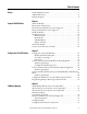
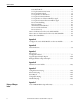
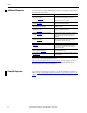
Table of Contents Preface Studio 5000 Environment . . . . . . . . . . . . . . . . . . . . . . . . . . . . . . . . . . . . . . . . . . 7 Additional Resources . . . . . . . . . . . . . . . . . . . . . . . . . . . . . . . . . . . . . . . . . . . . . . . 8 Example Programs . . . . . . . . . . . . . . . . . . . . . . . . . . . . . . . . . . . . . . . . . . . . . . . . . 8 Chapter 1 Compact I/O ASCII Module About the Module . . . . . . . . . . . . . . . . . . . . . . . . . . . . . . . . . . . . . . . . . . . .
Table of Contents Data Buffer Mode . . . . . . . . . . . . . . . . . . . . . . . . . . . . . . . . . . . . . . . . . . . . Set Up the Data Frame Format . . . . . . . . . . . . . . . . . . . . . . . . . . . . . . . . Receive Delimiter Mode. . . . . . . . . . . . . . . . . . . . . . . . . . . . . . . . . . . . . . . Set Up the Receive Delimiters . . . . . . . . . . . . . . . . . . . . . . . . . . . . . . . . . Set Up the Transmit Delimiter . . . . . . . . . . . . . . . . . . . . . . . . . . . . . . . .
Preface This manual describes how to install, configure, and troubleshoot your Compact I/O™ 1769-ASCII module. You must be able to use RSLogix™ software and the Studio 5000 Logix Designer™ application to configure this module. The 1769-ASCII module, a general-purpose two-channel ASCII interface, provides a flexible network interface to a wide variety of RS-232, RS-485, and RS-422 ASCII devices.
Preface Additional Resources These documents contain additional information concerning related products from Rockwell Automation. Resource Description CompactLogix 5370 L3 Controllers, Revision 20 Release Notes 1769-RN020 Describes enhancements, known anomalies, and restrictions for CompactLogix 5370 L3 controllers, firmware revisions 20.011…20.
Chapter 1 Compact I/O ASCII Module The 1769-ASCII module provides a flexible network interface to a wide variety of RS-232, RS-485, and RS-422 ASCII devices.
Chapter 1 Compact I/O ASCII Module Environment and Enclosure WARNING: This equipment is intended for use in a Pollution Degree 2 industrial environment, in overvoltage Category II applications (as defined in IEC publication 60664-1), at altitudes up to 2000 meters (6562 ft) without derating. This equipment is considered Group 1, Class A industrial equipment according to IEC/CISPR Publication 11.
Compact I/O ASCII Module Chapter 1 North American Hazardous Location Approval The following information applies when operating this Informations sur l’utilisation de cet équipement en equipment in hazardous locations. environnements dangereux. Products marked `CL I, DIV 2, GP A, B, C, D’ are suitable for use in Class I Division 2 Groups A, B, C, D, Hazardous Locations and nonhazardous locations only.
Chapter 1 Compact I/O ASCII Module European Hazardous Location Approval European Zone 2 Certification (The following applies when the product bears the Ex or EEx Marking.
Compact I/O ASCII Module Install the Module Chapter 1 Compact I/O is suitable for use in an industrial environment when installed in accordance with these instructions. Specifically, this equipment is intended for use in clean, dry environments (Pollution Degree 2(1)) and to circuits not exceeding Over Voltage Category II(2) (IEC 60664-1).(3) ATTENTION: Preventing Electrostatic Discharge This equipment is sensitive to electrostatic discharge, which can cause internal damage and affect normal operation.
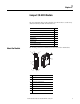
Chapter 1 Compact I/O ASCII Module Assemble the System Attach the module to the controller or an adjacent I/O module before or after mounting. For mounting instructions, see the Panel Mount or DIN Rail Mount sections. To work with a system that is already mounted, see Replace a Module section. 3 4 2 1 6 1 5 1. Disconnect power. ATTENTION: Remove power before removing or inserting this module. When you remove or insert a module with power applied, an electrical arc can occur.
Compact I/O ASCII Module Chapter 1 9. Lock the end-cap bus terminator (6). You must use a 1769-ECR or 1769-ECL right- or left-end cap to terminate the end of the serial communication bus. IMPORTANT Minimum Space Maintain spacing, for example, from enclosure walls, wireways, adjacent equipment. Allow 50 mm (2 in) of space on all sides for adequate ventilation.
Chapter 1 Compact I/O ASCII Module Panel Mount Procedure with Modules as a Template The following procedure lets you use the assembled modules as a template for drilling holes in the panel. Due to module mounting hole tolerance, it is important to follow these procedures. 1. On a clean work surface, assemble no more than three modules. 2. Mark the center of all module-mounting holes on the panel by using the assembled modules as a template. 3.
Compact I/O ASCII Module Chapter 1 Replace a Module The module can be replaced while the system is mounted to a panel or DIN rail. 1. Remove power. ATTENTION: Remove power before removing or inserting this module. When you remove or insert a module with power applied, an electrical arc can occur.
Chapter 1 Compact I/O ASCII Module Connect the D-sub Connector Pins All the pins are always active. Pins unused for a particular physical network must not be connected via the serial cable to any other device. In particular, do not use cables 1747-CP3 and 1756-CP3.
Compact I/O ASCII Module Chapter 1 Figure 2 - RS-232 Wiring Diagram - Module to Printer (hardware handshaking enabled, standard printer adapter cable) ASCII DTE 1 DTE 6 7 8 9 NC RTS CTS N.C.
Chapter 1 Compact I/O ASCII Module Notes: 20 Rockwell Automation Publication 1769-UM012B-EN-P - January 2014
Chapter 2 Configure the 1769-ASCII Module This chapter describes how to configure and program the 1769-ASCII module with CompactLogix controllers and the MicroLogix 1500 controller. Starting on page 34, there are three example Logix Designer programs using the 1769-ASCII module’s Add-On Profile. The examples use the Add-On Profile instead of the generic module profile. Using the Add-On Profile saves you time by making the configuration of the module easier, for example, not having to input a lot of data.
Chapter 2 Configure the 1769-ASCII Module 2. In the Enter test search or module type field, type 1769-ASCII or clear the checkboxes and check Specialty. 3. Select the 1769-ASCII module and click Create. 4. Close the Select Module Type dialog box. TIP If you are using RSLogix5000 software, version 16 and later and do not see the 1769-ASCII module as an option, you must download the module’s Add-On Profile. The Add-On Profile can be downloaded and installed from https:// download.rockwellautomation.
Configure the 1769-ASCII Module Chapter 2 The Module Properties Dialog box appears. 6. Review and make sure you have the correct module. 7. Type a name. 8. Type a description, if needed. 9. Assign a slot number to the module. 10. Review the Module Definition area and make sure the information is correct. 11. Click Change on the General tab to modify the module definition parameters. The Module Definition box appears.
Chapter 2 Configure the 1769-ASCII Module Module Definition Dialog Box The Module Definition dialog box contains a set of configuration parameters that affects data transmission between the controller and the I/O module. TIP Online edits are not possible when the controller is in RUN mode. Online edits must be made only when the controller is in Remote Run or Program modes. The Change button on the Module Properties General tab provides access where the listed parameters can be changed.
Configure the 1769-ASCII Module Chapter 2 1. In the Module Definition dialog box click the Channel tab. 2. Configure channel parameters and click OK. Each channel can be configured for 4…200 characters. For Simultaneous Mode, the sum of Channel 1 and Channel 2 for Receive and Transmit characters cannot exceed 200 bytes. The module's RPI can be configured through Connection tab. RPI can be configured in multiples of 0.5. The RPI can be configured for 1.0 - 750.0 in multiples of 0.5ms.
Chapter 2 Configure the 1769-ASCII Module 1769-ASCII Module Connections Dialog Box This tab displays information about the condition of the connection between the module and the controller. TIP Online edits are not possible when the controller is in RUN mode. Online edits must be made only when the controller is in Remote Run or Program modes. Use this tab to define controller to module behavior.
Configure the 1769-ASCII Module Chapter 2 Table 2 - Connection Tab Descriptions Parameter Descriptions RPI Enter the requested rate of packet arrival (connection update rate). The RPI specifies the interval at which data is transmitted or received over a connection. When scanned on the local bus or over an EtherNet/IP network, I/O modules are scanned at the RPI specified in the module configuration. Typically, you configure an RPI in milliseconds (ms).
Chapter 2 Configure the 1769-ASCII Module 1769-ASCII Module Configuration Dialog Box Use this dialog box to configure the ASCII parameters. TIP Online edits to a module's configuration do not take effect until the module connection is reestablished. This can be done by inhibiting/uninhibited the module using the checkbox on Connection tab. The module operation is interrupted while connection is inhibited.
Configure the 1769-ASCII Module Chapter 2 Table 3 - Module Properties Dialog Box - Configuration Tab Parameter Descriptions (Continued) Parameter Description Stop Bits Choose 1 or 2 (default) for the Stop Bits. Stop Bits appear dimmed Run mode.
Chapter 2 Configure the 1769-ASCII Module 1769-ASCII Module Advanced Configuration Dialog Box Use this dialog box to configure advanced parameters, such as receiving and transmitting data.
Configure the 1769-ASCII Module Chapter 2 Table 4 - Advanced Configuration Parameters Descriptions Parameter Description Channel Choose the channel (0 or 1) for which parameters are configured. Receive Data Byte Swap Mode These are the valid values. • Disabled (default) • 2 – bytes • 4 – bytes Byte Swap Mode appears dimmed in Run mode. Handshake Mode These are the valid values. • Master/Slave • Immediate (default) • Handshake Mode appears dimmed in Run mode.
Chapter 2 Configure the 1769-ASCII Module Controller-scoped Tags This is an example of a Controller-Scoped configuration tags. Data Types These are the Module-Defined data types that are used in the following exercises. The 1769-ASCII Add-On Profile displays the data types with a descriptive name. These dialog boxes differ slightly depending on whether you select Alternating or Simultaneous mode.
Configure the 1769-ASCII Module Chapter 2 This is an example of Module-Defined data types.
Chapter 2 Configure the 1769-ASCII Module Connect to Channel 0 of the Module in Alternating Mode This example program illustrates connecting the serial cable from your computer to channel 0 of the 1769-ASCII module in alternating mode. For more detailed information about the Alternate and Simultaneous modes, see I/O Memory Mapping on page 71. To access the Logix Designer programs, see the Knowledgebase Technote # 64203 at https://rockwellautomation.custhelp.com/app/answers/detail/a_id/ 64203.
Configure the 1769-ASCII Module Chapter 2 Ladder Logic Example This example illustrates connecting the cable from your computer to channel 0 of the 1769-ASCII module in alternating mode. This is the ladder logic in the Logix Designer program, L35ERM_QuickStart_002_V16.ACD. Main Routine The Main Routine resets the values of input and output lengths. This zeroes the data in and out.
Chapter 2 Configure the 1769-ASCII Module Input Ladder The Input ladder does the following tasks: • Moves the RxID for Channel 0, at first scan, to the OldRx. This identifies the initial RxID number. • Moves to see if the current RxID has changed that tells when the Data is in the buffer ready to be moved. • Receives data and then the data is copied. A Latched bit is set that identifies when the data has been copied to complete action on the new data.
Configure the 1769-ASCII Module Chapter 2 Output Ladder The Output ladder moves the data in the tag. OutData moves it to the output buffer then changes the transaction ID to send the data out.
Chapter 2 Configure the 1769-ASCII Module Configure the Module Properties Use the Module Properties dialog box to configure parameters for the module. The following screens illustrate example module settings.
Configure the 1769-ASCII Module Chapter 2 1769-ASCII Module Connection Dialog Box 1769-ASCII Module Configuration Dialog Box Rockwell Automation Publication 1769-UM012B-EN-P - January 2014 39
Chapter 2 Configure the 1769-ASCII Module 1769-ASCII Module Advanced Configuration Dialog Box 40 Rockwell Automation Publication 1769-UM012B-EN-P - January 2014
Configure the 1769-ASCII Module Connect to Both Channels of the Module in Alternating Mode Chapter 2 This example program illustrates connecting the serial cable from your computer to both channels of the 1769-ASCII module in alternating mode. For more detailed information about the Alternate and Simultaneous modes, see I/O Memory Mapping on page 71.
Chapter 2 Configure the 1769-ASCII Module Ladder Logic Example This ladder logic example illustrates how to connect to both channels of the module in alternating mode. This is the ladder logic in the Logix Designer program, L35ERM_QuickStart_003_V16.ACD Main Routine The Main Routine Zeros out the InData & OutData array lengths.
Configure the 1769-ASCII Module Chapter 2 Input Channel0 The Input Channel0 does the following tasks: • On first scan, stores current value of Rx0 Transaction ID (channel 0) as ‘most recent’. • Monitors the Rx0 Transaction ID.
Chapter 2 Configure the 1769-ASCII Module Input Channel1 The Input Channel1 does the following tasks: • On first scan, store current value of Rx1 Transaction ID (channel 1) as ‘most recent’ • When the Rx Transaction ID changes, it indicates there is ‘new data.’ • Copies data from the module's Input Tags to a STRING tag (InData1) if CNI = 1. • Indicates to the MainRoutine that new data has arrived. Saves this value of Rx Transaction ID, so you can detect the next change.
Configure the 1769-ASCII Module Chapter 2 Output Channel0 The Output Channel0 does the following tasks: • Sets the length in the module's output tag to the number of characters to be sent. • Copies the data from the STRING (OutData0) to the module's output tag. • If CN0 = 0, manually triggers the Tx Transaction ID in the 1769-ASCII Module's output tag. This tells it that you have some data for it to send.
Chapter 2 Configure the 1769-ASCII Module Output Channel1 The Output Channel1 does the following tasks: • Sets the length in the module's output tag to the number of characters to be sent. • Copies data from the STRING (OutData1) to the module's output tag. • If CN0 = 1, manually triggers the Tx Transaction ID in the module's output tag. This tells it that you have some data for it to send.
Configure the 1769-ASCII Module Chapter 2 1769-ASCII Module General Dialog Box 1769-ASCII Module Connection Dialog Box Rockwell Automation Publication 1769-UM012B-EN-P - January 2014 47
Chapter 2 Configure the 1769-ASCII Module 1769-ASCII Module Configuration Dialog Box 1769-ASCII Module Advanced Configuration Dialog Box 48 Rockwell Automation Publication 1769-UM012B-EN-P - January 2014
Configure the 1769-ASCII Module Connect to Both Channels of the 1769-ASCII Module in Simultaneous Mode Chapter 2 This example program illustrates connecting the serial cable from your computer to both channels of the 1769-ASCII module. TIP See Connect the D-sub Connector Pins on page 18 for detailed information on how to build the appropriate cable for the RS-232 connection between PC with a serial port and the 1769-ASCII module D-sub connector.
Chapter 2 Configure the 1769-ASCII Module Ladder Logic Example This is the ladder logic in the Logix Designer project, L35ERM_QuickStart_004_V16.ACD. This example program illustrates connecting the cable from your computer to both channels of the 1769-ASCII module. Main Routine The Main Routine zeros out the InData & OutData arrays.
Configure the 1769-ASCII Module Chapter 2 Input Channel0 The Input Channel0 does the following tasks: • Stores the current value, on the first scan, as the current value of Rx0 Transaction ID (channel 0) as most recent.
Chapter 2 Configure the 1769-ASCII Module Input Channel1 The Input Channel1 does the following tasks: • Stores the current value, on first scan, of Rx Transaction ID (channel 1) as most recent. • Monitors the lower 8 bits of Rx Transaction ID (upper 8 bit are Tx) • Indicates new data when the Rx Transaction ID changes. • Copies the data from the module's Input Tags to a STRING tag (InData1). • Indicates to the MainRoutine that new data has arrived.
Configure the 1769-ASCII Module Chapter 2 Output Channel0 The Output Channel0 does the following tasks: • Copies the data from the STRING (OutData0) to the module's output tag. • Copies the Length of the number of bytes of the OutputData0 array. • Triggers the Tx Transaction ID in the module's output tag. This tells it that you have some data for it to send.
Chapter 2 Configure the 1769-ASCII Module Output Channel1 The Output Channel1 does the following tasks: • Copies data from the STRING (OutData1) to the module's output tag. • Copies the Length of the number of bytes of the OutputData1 array. • Triggers the Tx Transaction ID in the module's output tag. This tells it that you have some data for it to send.
Configure the 1769-ASCII Module Chapter 2 When the I/O module properties appear, enter the following information: a name, the appropriate slot number, specify a Comm Format of Data_INT, and enter the following values: Data Type: AB:1769_ASCII:C:0 Data Type: AB:1769_ASCII_80Bytes_80Bytes:I:0 Rockwell Automation Publication 1769-UM012B-EN-P - January 2014 55
Chapter 2 Configure the 1769-ASCII Module Data Type: AB:1769_ASCII_80Bytes_80Bytes:O:0 1769-ASCII Module General Dialog Box 56 Rockwell Automation Publication 1769-UM012B-EN-P - January 2014
Configure the 1769-ASCII Module Chapter 2 1769-ASCII Module Connection Dialog Box 1769-ASCII Module Configuration Dialog Box Rockwell Automation Publication 1769-UM012B-EN-P - January 2014 57
Chapter 2 Configure the 1769-ASCII Module 1769-ASCII Module Advanced Configuration Dialog Box 58 Rockwell Automation Publication 1769-UM012B-EN-P - January 2014
Configure the 1769-ASCII Module Configure the Module for Use with a MicroLogix Controller Chapter 2 To work with the MicroLogix controller, follow these instructions to prepare the 1769-ASCII module. 1. Open your project. 2. Right-click the 1769-ASCII module and choose Properties. Make sure Series and Revision match with the hardware. 3. Review and make sure you have the correct module. 4. Type a name. 5. Type a Description. 6. Review the Module Definition area and make sure the information is correct.
Chapter 2 Configure the 1769-ASCII Module 8. Configure channel parameters under the channel tab. Each channel can be configured for 4…200 characters. For Simultaneous Mode, the sum of Channel 1 and Channel 2 for Receive and Transmit characters cannot exceed 200 bytes. 9. Module's RPI can be configured through Connection tab. RPI can be configured in multiples of 0.5.
Configure the 1769-ASCII Module Chapter 2 10. ASCII protocol configuration can be done under Configuration tab. Channels 0 and 1 can have different configuration. Advanced ASCII protocol configuration like Byte Swap Mode can be done under Advanced Configuration tab. Channels 0 and 1 can have different advanced configurations.
Chapter 2 Configure the 1769-ASCII Module Programming Example: MicroLogix 1500 Controller This MicroLogix example demonstrates how the 1769-ASCII module's channel 0 collects a line of input from the HyperTerminal and echoes that line to you. To make sure your 1769-ASCII module is functioning properly, follow these instructions. 1. Open the RSLogix 500 software. 2. Create a project. In this example, the name of the project is Micro1500_Quickstart_001. 3.
Configure the 1769-ASCII Module Chapter 2 9. From the Generic Extra Data Config tab, enter your application data by referring to the Configuration File. 10. Click OK. 11. Create your program by using these tags.
Chapter 2 Configure the 1769-ASCII Module The RSLogix 500 software has data files in the project space to create different tags. In this example, the following tags were used.
Configure the 1769-ASCII Module Rockwell Automation Publication 1769-UM012B-EN-P - January 2014 Chapter 2 65
Chapter 2 Configure the 1769-ASCII Module • Output 66 Rockwell Automation Publication 1769-UM012B-EN-P - January 2014
Configure the 1769-ASCII Module Rockwell Automation Publication 1769-UM012B-EN-P - January 2014 Chapter 2 67
Chapter 2 Configure the 1769-ASCII Module • Transfer from input to output This figure indicates that the output is triggered when input is received. 12. Download your program to the controller. 13. Place the controller in Run mode. 14. Connect the computer to the 1769-ASCII module. Connect channel 0 of the 1769-ASCII module to a COM port of your computer with a cable constructed per the specifications on page 21. 15. Run the HyperTerminal application. 16.
Configure the 1769-ASCII Module Chapter 2 The 1769-ASCII module returns text data entered into Outdata tag back to your screen. This is not an echo program. Input is received and stored in a string file Indata (ST11:0). New data triggers the output from another file Outdata (ST11:1). The data back on the terminal is not the same as the data sent from the terminal. You must put in a data string in Outdata (ST11:1) before running the program.
Chapter 2 Configure the 1769-ASCII Module Notes: 70 Rockwell Automation Publication 1769-UM012B-EN-P - January 2014
Chapter 3 I/O Memory Mapping When both serial channels are active, you can alternate between receiving data in the buffer from both ports simultaneously or one at a time. ASCII Module Behavior when not in Run Mode The 1769-ASCII module transmits data out the serial port when the controller is only in Run mode. It sends data once the Tx Transaction ID changes after the controller transitions into Run mode.
Chapter 3 I/O Memory Mapping The alternate mode output file contains the real-time output data from the module. This table shows the generic module tag definitions on the left. On the right of the table is the 1769-ASCII module Add-On Profile configuration using RSLogix 5000 software version 16 and later. Alternate Mode (one channel at a time) Output File It is assumed that 16 bit words are used. The structure on the left is used with varying data types; SINT, INT, BOOL and SINT array for data.
I/O Memory Mapping Alternate Mode (one channel at a time) Input File Chapter 3 One channel’s data is received and stored in the input file at a time. The Channel Number (CN) bit defines the channel whose data is returned. The alternate mode input file contains the real-time input data from the module with a header and data section for each channel. This table illustrates the maximum size allowed.
Chapter 3 I/O Memory Mapping In Simultaneous mode, the data is packed in the buffer as follows: • Four words of channel 0 header information • Channel 0 data of a quantity defined by the Max_Receive_Size parameter • Four words of channel 1 header information • Channel 1 data of a quantity defined by the Max_Receive_Size parameter Simultaneous Mode (two channels) Input File This table illustrates the maximum size allowed.
I/O Memory Mapping Chapter 3 In simultaneous mode, the data is packed in the buffer as follows: • Four words of channel 0 header information • Channel 0 data of a quantity defined by the Max_Receive_Size parameter • Four words of channel 1 header information • Channel 1 data of a quantity defined by the Max_Receive_Size parameter Simultaneous Mode (two channels) Output File This table illustrates the maximum size allowed.
Chapter 3 I/O Memory Mapping Status Descriptions This table describes the status tags. 76 Add-On Profile Abbr. Definition ChxHandshakeError HE Handshake error. Used for Handshake mode only. ChxNewData ND New data. Used for Handshake mode only. ChxNonDelimitedRecord NR Non-delimited record. An input record is received and sent to the Compactbus interface that was not triggered by receiving a delimiter character.
I/O Memory Mapping Chapter 3 The 1769-ASCII module supports a configuration assembly that is configured with the Add-On Profile.
Chapter 3 I/O Memory Mapping Tag Definition Word Table 9 - Configuration File Tag Names (Continued) Description Values Valid Data Values Channel 1 Module Properties Dialog Box 16 Serial Character Framing 0…8 0 = 7N2, 1 = 7E1, 2 = 7O1, 3 = 8N1, 4 = 8N2, 5 = 8E1, 6 = 8O1, 7 = 7E2, 8 = 7O2 CH1BaudRate Serial Port Speed 0…7 0 = 9600, 1 = 1200, 2 = 2400, 3 = 4800, 4 = 19200, 5 = 38400, 6 = 57.6k, 7 = 115.
I/O Memory Mapping Configuration File Parameter Operation Chapter 3 Each channel’s serial port and data string operation is configured individually and independently. The parameters that are not independent are the Data Buffer mode and the Transmit and Receive buffer sizes. The sum of the two channels’ buffer sizes cannot total more than 200 bytes, in each direction, while using the Simultaneous Buffer mode.
Chapter 3 I/O Memory Mapping Set Up the Receive Delimiters The receive Start Delimiter is a start-of-string character used by the 1769-ASCII module to determine that the first expected character from the ASCII device is received. Upon receipt of this character, the 1769-ASCII module starts storing the string data in its internal data buffer on the serial receive side.
I/O Memory Mapping Chapter 3 Set Up the Transmit Delimiter The 1769-ASCII module uses the transmit (and exclude) delimiter to determine the number of bytes to transmit to your ASCII device. The 1769-ASCII module transmits up to and including the delimiter when the length in the output file is 0. If the output file length is not 0, the 1769-ASCII module transmits the number of bytes/characters specified in the header's length value.
Chapter 3 I/O Memory Mapping Set Up the Transmit Character Buffer Length The Transmit Character Buffer Length parameter is the number of characters that the 1769-ASCII module can receive in its transmit buffer from the CompactBus Master. This size value determines the maximum size of the command data sent to the 1769-ASCII module from the Master, that is the 1769-ASCII module Consume Size.
I/O Memory Mapping Chapter 3 Byte Swap Mode To help with compatibility with end serial devices, the 1769-ASCII module supports user-configurable options to byte swap data received from or transmitted to the ASCII devices. Byte swapping of data is supported on 16- or 32-bit boundaries. When Byte Swap mode is enabled, the user-defined Receive/Transmit Buffer Length parameters must be evenly divisible by the bit boundary, 16- or 32-bit.
Chapter 3 I/O Memory Mapping Receive Timeout The 1769-ASCII module has a receive timeout value configurable in 1 ms increments. The timeout counter resets on the receipt of each new byte of data. If the timeout counter expires, the 1769-ASCII module sets the Non-Delimited flag in the Status Byte and updates the Receive/Produce buffer with the current data string.
I/O Memory Mapping How to Receive Serial Data from the 1769-ASCII Module Chapter 3 The Produce buffer can include one channel's data or combine both channel's data in one buffer from the 1769-ASCII module to the CompactBus Master. If you configure the module to return only one channel's data in the Produce buffer, the channel can return up to 200-bytes of ASCII data. A CN0 bit in the Consume buffer is allocated to determine which channel’s ASCII data the CompactBus Master is actively requesting.
Chapter 3 I/O Memory Mapping Notes: 86 Rockwell Automation Publication 1769-UM012B-EN-P - January 2014
Appendix A Configure the 1769-ASCII Module as a Generic Module This example demonstrates a CompactLogix program using channel 0 of the ASCII module to collect a line of input from HyperTerminal and echo that line back to you. For information on the MicroLogix controller, see Configure the Module for Use with a MicroLogix Controller on page 57. Use the following quick start to make sure your ASCII module is functioning properly. 1. Open Logix Designer software. 2. Create a new project.
Appendix A Configure the 1769-ASCII Module as a Generic Module 6. Open the controller tags for monitor to enter the following configuration parameters in the Local::C tag data members. All other parameters are 0.
Configure the 1769-ASCII Module as a Generic Module Appendix A 7. Create your program using these tags.
Appendix A Configure the 1769-ASCII Module as a Generic Module 8. Create two ladder routines in the MainProgram, named Input and Output. This is the main routine.
Configure the 1769-ASCII Module as a Generic Module Appendix A 9.
Appendix A Configure the 1769-ASCII Module as a Generic Module • output 92 Rockwell Automation Publication 1769-UM012B-EN-P - January 2014
Configure the 1769-ASCII Module as a Generic Module Appendix A • transfer from input to output 10. Download your program to the controller. 11. Place the controller in Run mode. 12. Connect channel 0 of the ASCII module to a COM port of your computer. 13. Run HyperTerminal. 14. Configure HyperTerminal so that the configuration matches the ASCII device for baud rate and framing. 15. Turn off flow control. 16. In HyperTerminal, type in a value. Type some text into HyperTerminal.
Appendix A Configure the 1769-ASCII Module as a Generic Module Notes: 94 Rockwell Automation Publication 1769-UM012B-EN-P - January 2014
Appendix B INTERFACE Status Indicators OK RX0 TX0 RX1 TX1 ASCII The following table defines the 1769-ASCII module status indicators. Status Indicator State Meaning OK Off No power, module is not configured, or no bus master Solid green In run mode.
Appendix B Status Indicators Notes: 96 Rockwell Automation Publication 1769-UM012B-EN-P - January 2014
Appendix C Error Codes This table indicates the error codes that are associated with the 1769-ASCII module. Table 10 - 1769-ASCII Module Error Codes Configuration Errors Value (Hex) Meaning 0 No error 200…3FF Hardware error 400…5FF Configuration error 800…DFF Reserved for future use E00…FFF Bus master detected error This table indicates the error codes that are associated with configuration errors.
Appendix C Error Codes This table indicates the error codes that are associated with Channel 0. Table 12 - Channel 0 Module Configuration Errors 98 Value (Hex) Meaning Description 430 Data buffer mode 0 = alternate mode; 1 = simultaneous mode. Anything else is invalid. 440 Invalid serial port framing The serial port framing specified is invalid. 441 Invalid serial port speed The serial port speed specified is invalid.
Error Codes Appendix C This table indicates the error codes that are associated with Channel 1. Table 13 - Channel 1 Module Configuration Errors Value (Hex) Meaning Description 480 Invalid serial port framing The serial port framing specified is invalid. 481 Invalid serial port speed The serial port speed specified is invalid. 482 Invalid max number of receive characters The maximum number of receive characters specified for channel 1 is too large.
Appendix C Error Codes Logix Designer Example Report To generate a report in Logix Designer, follow these instructions. 1. From the File menu, choose Generate Report. 2. Select what you want to see in the report. 3. Print to a PDF file or another format.
Error Codes Rockwell Automation Publication 1769-UM012B-EN-P - January 2014 Appendix C 101
Appendix C Error Codes RSLogix 500 Error Report Example IMPORTANT If a 1769 I/O module fault occurs, you must cycle power to the controller after clearing the major fault. I/O communication is not restored until after the power cycle. Never use the fault handling routine to clear local I/O faults. Clear local I/O faults manually on a per instance basis, and then cycle power to the controller.
Appendix D ASCII Conversion Tables The following table defines the conversions between decimal, octal, hex, and binary values and the ASCII character or control associated with that value.
Appendix D ASCII Conversion Tables Table 14 - ASCII Conversions (Continued) Decimal Octal Hex Binary ASCII Character or Control Decimal Octal Hex Binary ASCII Character or Control 53 65 35 0110101 5 88 130 58 1011000 X 54 66 36 0110110 6 89 131 59 1011001 Y 55 67 37 0110111 7 90 132 5A 1011010 Z 56 70 38 0111000 8 91 133 5B 1011011 [ 57 71 39 0111001 9 92 134 5C 1011100 \ 58 72 3A 0111010 : 93 135 5D 1011101 ] 59 73 3B 0111011 ; 94
Appendix E Using Electronic Keying Electronic Keying Topic Page Electronic Keying 105 Exact Match 106 Compatible Keying 107 Disabled Keying 109 The electronic keying feature automatically compares the expected module, as shown in the Logix Designer I/O Configuration tree, to the physical module before I/O communication begins. You can use electronic keying to help prevent communication to a module that does not match the type and revision expected.
Appendix E Using Electronic Keying You can find revision information on the General tab of a module’s Properties dialog box. Figure 5 - General Tab IMPORTANT Exact Match Changing electronic keying selections online may cause the I/O communication connection to the module to be disrupted and may result in a loss of data.
Using Electronic Keying Appendix E Firmware Update for the module via the Firmware Supervisor feature from a Logix5000 controller. EXAMPLE In the following scenario, Exact Match keying prevents I/O communication. The module configuration is for a 1756-IB16D module with module revision 3.1. The physical module is a 1756-IB16D module with module revision 3.2. In this case, communication is prevented because the Minor Revision of the module does not match precisely.
Appendix E Using Electronic Keying 1756-CNBR module with a 1756-CN2R module. The release notes for individual modules indicate the specific compatibility details. When a module is created, the module developers consider the module’s development history to implement capabilities that emulate those of the previous module. However, the developers cannot know future developments.
Using Electronic Keying EXAMPLE Appendix E In the following scenario, Compatible Keying allows I/O communication: The module configuration is for a 1756-IB16D module with module revision 2.1. The physical module is a 1756-IB16D module with module revision 3.2. In this case, communication is allowed because the major revision of the physical module is higher than expected and the module determines that it is compatible with the prior major revision.
Appendix E Using Electronic Keying If you use Disabled Keying, you must take full responsibility for understanding whether the module being used can fulfill the functional requirements of the application. EXAMPLE In the following scenario, Disable Keying prevents I/O communication. The module configuration is for a 1756-IA16 digital input module. The physical module is a 1756-IF16 analog input module.
Using Electronic Keying EXAMPLE Appendix E In the following scenario, Disable Keying allows I/O communication. The module configuration is for a 1756-IA16 digital input module. The physical module is a 1756-IB16 digital input module. In this case, communication is allowed because the two digital modules share common data formats. Module Configuration Vendor = Allen-Bradley Product Type = Digital Input Module Catalog Number = 1756-IA16 Major Revision = 2 Minor Revision = 1 Communication is allowed.
Appendix E Using Electronic Keying Notes: 112 Rockwell Automation Publication 1769-UM012B-EN-P - January 2014
Appendix F History of Changes This appendix summarizes the revisions to this manual. Reference this appendix if you need information to determine what changes have been made across multiple revisions. This can be especially useful if you are deciding to upgrade your hardware or software based on information added with previous revisions of this manual. 1769-UM012B-EN-P September 2013 • • • • • • • • • • • Added 1769-ASCII module AOP tag definitions.
Appendix F History of Changes Notes: 114 Rockwell Automation Publication 1769-UM012B-EN-P - January 2014
Index Numerics 1769-ASCII module status indicators 95 1769-ECL 15 1769-ECR 15 A Add-On Profile 79 alternating mode both channels 41 input Channel 0 43 input Channel 1 44 input file 73 output Channel 0 45 output Channel 1 46 output file 72 AOP 21 ASCII module Add-On Profile 21 AOP 21 communication connections 9 configure 21 description 9 DIN rail mount 16 ground 13, 17 intall 13 interface 7 mount 14 panel mount 15 replace 17 attributes keying 105 D data bits 28 buffer 79 buffer mode 79 format 24 format typ
Index K keying about 105 attributes 105 compatible 107 L ladder logix example 35 Logix Designer 7, 8, 21, 34, 41, 49 M major fault 27 MicroLogix 21 ASCII protocol 25, 61 configure 59 example 62 mode alternating 24, 34, 35, 41, 79 silutaneous 75 simultaneous 24, 49, 79 module fault 27 mounting screws 15 O online edits 24, 28 output data writing serial output 85 output file alternate mode 72 simultaneous mode 75 output ladder 37 P panel mount 14, 15 parameter operation configuration file 79 parity 28 R
Rockwell Automation Support Rockwell Automation provides technical information on the Web to assist you in using its products. At http://www.rockwellautomation.com/support you can find technical and application notes, sample code, and links to software service packs. You can also visit our Support Center at https://rockwellautomation.custhelp.com/ for software updates, support chats and forums, technical information, FAQs, and to sign up for product notification updates.