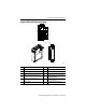
Installation Instructions Compact I/O 1769-ADN DeviceNet Adapter Cat. No.
Compact I/O 1769-ADN DeviceNet Adapter Important User Information Solid-state equipment has operational characteristics differing from those of electromechanical equipment. Safety Guidelines for the Application, Installation and Maintenance of Solid State Controls (publication SGI-1.1 available from your local Rockwell Automation sales office or online at http://www.rockwellautomation.
Compact I/O 1769-ADN DeviceNet Adapter 3 Environment and Enclosure ATTENTION: This equipment is intended for use in a Pollution Degree 2 industrial environment, in overvoltage Category II applications (as defined in IEC publication 60664-1), at altitudes up to 2000 meters without derating. ATTENTION: This equipment is considered Group 1, Class A industrial equipment according to IEC/CISPR Publication 11.
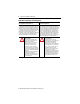
Compact I/O 1769-ADN DeviceNet Adapter North American Hazardous Location Approval The following information applies when operating this equipment in hazardous locations. Informations sur l’utilisation de cet équipement en environnements dangereux. Products marked "CL I, DIV 2, GP A, B, C, D" are suitable for use in Class I Division 2 Groups A, B, C, D, Hazardous Locations and nonhazardous locations only.
Compact I/O 1769-ADN DeviceNet Adapter 5 Compact I/O DeviceNet Adapter Description Comm Adapter 1a MS NS IO DIAG 2 8a 5 8b 3 9 1b Comm Adapter 6a MS NS IO DIAG 4 7 5 6b 42125 Item Description Item Description 1a Upper panel mounting tab 6a Upper DIN-rail latch 1b Lower panel mounting tab 6b Lower DIN-rail latch 2 I/O diagnostic LEDs 7 Write-on label (user I.D.
Compact I/O 1769-ADN DeviceNet Adapter Prevent Electrostatic Discharge ATTENTION: This equipment is sensitive to electrostatic discharge, which can cause internal damage and affect normal operation. Follow these guidelines when you handle this equipment: • • • • • • Touch a grounded object to discharge potential static. Wear an approved grounding wriststrap. Do not touch connectors or pins on component boards. Do not touch circuit components inside the equipment.
Compact I/O 1769-ADN DeviceNet Adapter 7 System Configurations Configuration Rules • The adapter must be the first and left-most module in the system (the first module of Bank 1). Refer to page 9 for an example configuration. • • • • The adapter can communicate with up to 30 modules in a system. An end cap/terminator must be on the last I/O bank. Each bank of I/O must have its own power supply.
Compact I/O 1769-ADN DeviceNet Adapter Where the “Number of Output Modules” is the number of output modules configured to have 1 or more words of output data. The maximum number of output words is distributed across all of the output modules. • The Series B adapter supports a maximum of 254 words (508 bytes) of configuration data for each individual module, for a total capacity of 7,620 words (15,240 bytes).
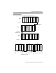
Compact I/O 1769-ADN DeviceNet Adapter 9 Example Configurations 1769 I/O 1769 I/O 1769-CRRx 1769 I/O 6 11 12 1769-CRRx 10 5 1769 I/O 9 4 1769 I/O 8 1769 I/O 1769 Power Supply 1769 I/O 7 I/O Slot Number 3 Right-to-Right Cable 1769 Power Supply 1769 I/O 2 1769 I/O Bank 2 1 1769 I/O 1769-CLLx I/O Slot Number 1769 I/O Bank 1 1769 I/O 1769-ADN The following illustrations show examples of two valid system setups.
Compact I/O 1769-ADN DeviceNet Adapter System Assembly The adapter can be attached to adjacent 1769 modules before or after mounting. • For mounting instructions, see Panel Mounting on page 11, or DIN Rail Mounting on page 12. • To work with a system that is already mounted, see Replacing the 1769-ADN within a System on page 13. The following procedure shows you how to assemble the Compact I/O™ system. a b c a e 1769-ADN a a d 42126 1. Disconnect power. 2.
Compact I/O 1769-ADN DeviceNet Adapter 11 Mounting the Adapter and I/O Modules ATTENTION: During panel or DIN rail mounting of all devices, be sure that all debris (metal chips, wire strands, etc.) is kept from falling into the adapter or modules. Debris that falls into the adapter or modules could cause damage on power up. Minimum Spacing Maintain spacing from enclosure walls, wireways, adjacent equipment, etc.
Compact I/O 1769-ADN DeviceNet Adapter Panel Mounting Procedure Using Modules as a Template The following procedure allows you to use the assembled adapter and modules as a template for drilling holes in the panel. If you have sophisticated panel mounting equipment, you can use the dimensional template provided on page 11. Due to the module mounting hole tolerance, it is important to follow these procedures: 1. On a clean work surface, assemble no more than three modules. 2.
Compact I/O 1769-ADN DeviceNet Adapter 13 Replacing the 1769-ADN within a System Same Series Replacement When replacing an adapter with another adapter of the same series, you may need to use RSNetWorx™ for DeviceNet software to change the minor firmware revision if the adapter’s electronic keying option is set to Exact Match.
Compact I/O 1769-ADN DeviceNet Adapter RSNetWorx version 4.01 (or later) provides an updated configuration GUI with expanded functionality for Series B adapters. When a Series B adapter is used to replace a Series A adapter, this version of RSNetWorx converts the Series A adapter configuration information into the format required by the Series B adapter after following these steps: 1. Upgrade your version of RSNetWorx to version 4.01 or later. 2. Open up the RSNetWorx file (*.
Compact I/O 1769-ADN DeviceNet Adapter 15 Steps to Replace the Adapter The adapter can be replaced while the system is mounted to a panel (or DIN rail). 1. Remove power. See important note on page 6. 2. Remove the DeviceNet cable from the module by removing the connector. 3. Remove the upper and lower mounting screws from the adapter (or open the DIN latches using a flat-blade or phillips-style screwdriver). 4.
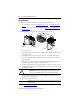
Compact I/O 1769-ADN DeviceNet Adapter Comm Adapter DeviceNet Wiring MS NS IO DIAG DeviceNet Connector 42123 1. Connect the DeviceNet cable to the removable connector as shown. Connect To BLK Wire -V BLU Wire CAN Low Bare Wire Drain WHT Wire CAN High RED Wire +V BLK BLU Bare WHT RED Connector 42122 2. Insert the removable female connector into the mating male connector on the DeviceNet adapter module. 3.
Compact I/O 1769-ADN DeviceNet Adapter 17 Setting the Network Address Switches Set the network address with the two rotary switches. Use a small, slotted screwdriver to set the switches. The switch labeled MSD (Most Significant Digit) sets the 10s while the switch labeled LSD (Least Significant Digit) sets the 1s. Valid network addresses are 00 through 63. Switch settings from 00 to 63 select network addresses 00 to 63.
Compact I/O 1769-ADN DeviceNet Adapter Configuring the 1769-ADN Series B Adapter The 1769-ADN must be configured with RSNetWorx for DeviceNet software. This configuration tool allows you to identify all of the devices (I/O modules, power supplies, expansion cables, end caps) and their locations in your 1769 system. The 1769-ADN must have the I/O configuration loaded into its’ memory to perform the network communication function.
Compact I/O 1769-ADN DeviceNet Adapter 19 Input Data This is the I/O data the 1769-ADN sends to the DeviceNet master. All inputs are in words. For more information, refer to the Compact I/O 1769-ADN DeviceNet Adapter User Manual, publication 1769-UM001.
Compact I/O 1769-ADN DeviceNet Adapter Module Status Indicator I/O Status Indicator Comm Adapter Diagnostic Indicators MS NS IO DIAG Network Status Indicator Diagnostic Status Indicator 42128 Status Indicators Meaning Module Status (MS) OFF No power Flashing GRN/OFF On-line but configuration missing Solid GRN Device operational Flashing RED/OFF Recoverable fault • configuration incorrect • duplicate mac id (node address) check failed • node address switch changed • main program checksu
Compact I/O 1769-ADN DeviceNet Adapter 21 Status Indicators Meaning Network Status (NS) OFF No power or no network access Flashing GRN/OFF On-line but not connected Solid GRN On-line and connected Flashing RED/OFF Connection time-out Solid RED Critical network failure I/O Status (IO) OFF No power or outputs off Flashing GRN/OFF Idle/program mode - one or more I/O modules in Idle Mode Solid GRN Device operational - all I/O modules in Run Mode Flashing RED/OFF Recoverable fault - one or mo
Compact I/O 1769-ADN DeviceNet Adapter Specifications Specification Value Dimensions 118mm (height) x 87mm (depth) x 50mm (width) height including mounting tabs is 138mm 4.65in (height) x 3.43in (depth) x 1.97in (width) height including mounting tabs is 5.43in Approximate Shipping Weight (With Carton) 280g (0.
Compact I/O 1769-ADN DeviceNet Adapter 23 Specification Value Enclosure Type Rating None (open-style) Certifications (When Product is Marked) c-UL-us UL Listed for Class I, Division 2 Group A,B,C,D Hazardous Locations, certified for U.S. and Canada European Union 89/336/EEC EMC Directive, CE1 compliant with: - EN 50082-2; Industrial Immunity - EN 61326; Meas./Control/Lab.
Compact I/O 1769-ADN DeviceNet Adapter Additional Resources These documents contain additional information concerning related products from Rockwell Automation. Resource Description Industrial Automation Wiring and Grounding Guidelines, publication 1770-4.1 Provides general guidelines for installing a Rockwell Automation industrial system. Product Certifications website, http://www.ab.com Provides declarations of conformity, certificates, and other certification details.
Compact I/O 1769-ADN DeviceNet Adapter 25 Product Publication Publication Number Information on how to install and use your 1769-IF4 and -OF2 modules Compact 1769-IF4 and -OF2 Analog Modules User Manual 1769-UM002 Installation guides for 1769 Analog Compact I/O module 1769-IF4XOF2 * For DeviceNet Series B adapters only Compact 1769-IF4XOF2 Combination Analog Module Installation Instructions 1769-IN057 Information on how to install and use your 1769-IF4XOF2 module Compact 1769-IF4XOF2 8-Bit Low-Re
Compact I/O 1769-ADN DeviceNet Adapter Notes: Rockwell Automation Publication 1769-IN001C-EN-P - February 2013
Compact I/O 1769-ADN DeviceNet Adapter 27 Notes: Rockwell Automation Publication 1769-IN001C-EN-P - February 2013
Rockwell Automation Support Rockwell Automation provides technical information on the Web to assist you in using its products. At http://www.rockwellautomation.com/support, you can find technical manuals, technical and application notes, sample code and links to software service packs, and a MySupport feature that you can customize to make the best use of these tools. You can also visit our Knowledgebase at http://www.rockwellautomation.