Installation Instructions 1768 CompactLogix Power Supplies Catalog Numbers 1768-PA3, 1768-PB3 Topic Page Important User Information 2 About the 1768 Power Supplies 5 Safety Circuits 11 Main Power Disconnect 12 Install the Power Supply 16 Mount the Power Supply 16 Place 1769 I/O Modules in a 1768 CompactLogix System 22 Interpret the LED Indicators 23 Specifications 27 Additional Resources 31 About This Publication Use this publication to install the 1768-PA3 and 1768-PB3 CompactLogix
1768 CompactLogix Power Supplies Important User Information Solid state equipment has operational characteristics differing from those of electromechanical equipment. Safety Guidelines for the Application, Installation and Maintenance of Solid State Controls (publication SGI-1.1 available from your local Rockwell Automation sales office or online at http://literature.rockwellautomation.com) describes some important differences between solid state equipment and hard-wired electromechanical devices.
1768 CompactLogix Power Supplies 3 North American Hazardous Location Approval The following Information applies when operating this equipment in hazardous locations: Informations sur l'utilisation de cet équipement en environnements dangereux: Products marked "CL I, DIV 2, GP A, B, C, D" are suitable for use in Class I Division 2 Groups A, B, C, D, Hazardous Locations and nonhazardous locations only.
1768 CompactLogix Power Supplies Environment and Enclosure ATTENTION This equipment is intended for use in a Pollution Degree 2 industrial environment, in overvoltage Category II applications (as defined in IEC publication 60664-1), at altitudes up to 2000 meters (1.24 mi) without derating. This equipment is considered Group 1, Class A industrial equipment according to IEC/CISPR Publication 11.
1768 CompactLogix Power Supplies 5 Prevent Electrostatic Discharge ATTENTION This equipment is sensitive to electrostatic discharge, which can cause internal damage and affect normal operation. Follow these guidelines when you handle this equipment: • Touch a grounded object to discharge potential static. • Wear an approved grounding wriststrap. • Do not touch connectors or pins on component boards. • Do not touch circuit components inside the equipment. • Use a static-safe workstation, if available.
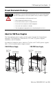
1768 CompactLogix Power Supplies 1768-PA3 Power Supply The 1768-PA3 power supply is a dual-input power supply that operates in multiple ranges. The 1768-PA3 offers the following input power supply options: • 85...265V ac • 108...132V dc 1768-PB3 Power Supply The 1768-PB3 power supply is a single-input power supply. The 1768-PB3 offers the following input power supply range: • 16.8...31.
1768 CompactLogix Power Supplies 7 The controller converts the 24V dc to 5V dc and distributes 5V dc and 24V dc power as required by modules on the backplane. The following list describes controller power distribution considerations: • 5V/24V power goes to 1769 I/O modules on the right side of the controller. • 5V power goes to 1768 communication or motion modules on the left side of the controller. • System power-up and power-down may take longer than expected.
1768 CompactLogix Power Supplies • The 1768 power supply has a different distance rating than the 1769 power supply. For more information, see Place 1769 I/O Modules in a 1768 CompactLogix System. Use a Fuse with the Power Supply The CompactLogix power supply has an internal, non-replaceable fuse soldered in place. This fuse is intended to guard against fire hazard due to short circuit conditions.
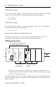
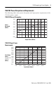
1768 CompactLogix Power Supplies 9 1768-PA3 Power Dissipation and Requirements The following tables show power dissipation and input power requirements of the 1768-PA3 power supply.
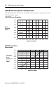
1768 CompactLogix Power Supplies 1768-PB3 Power Dissipation and Requirements The following tables show power dissipation and input power requirements of the 1768-PB3 power supply.
1768 CompactLogix Power Supplies 11 Safety Circuits WARNING Explosion Hazard - Do not connect or disconnect connectors while circuit is live. ATTENTION Circuits installed on the machine for safety reasons, like overtravel limit switches, stop push buttons, and interlocks, should always be hard-wired directly to the master control relay. These devices must be wired in series so that when any one device opens, the master control relay is de-energized, thereby removing power to the machine.
1768 CompactLogix Power Supplies Main Power Disconnect WARNING Explosion Hazard - Do not replace components or disconnect equipment unless power has been switched off. Place the main power disconnect switch where operators and maintenance personnel have quick and easy access to it. In addition to disconnecting electrical power, de-energize all other sources of power (pneumatic and hydraulic) before working on a machine or process controlled by a controller.
1768 CompactLogix Power Supplies 13 Additional considerations determine whether the power source must be required to supply high inrush current. • The power-up sequence of devices in a system • The amount of the power-source voltage sag if the inrush current cannot be supplied • The effect of voltage sag on other equipment in the system If the entire system is powered-up at the same time, a brief sag in the power source voltage typically does not affect equipment.
1768 CompactLogix Power Supplies Other Types of Line Conditions Occasionally the power source to the system can be temporarily interrupted. Also, it is possible that the voltage level may drop substantially below the normal linevoltage range for a period of time. Both the interruption and the voltage sag are considered power losses for the system. Master Control Relay A hard-wired master control relay (MCR) provides a reliable means for emergency machine shutdown.
1768 CompactLogix Power Supplies 15 The master control relay is not a substitute for a disconnect to the system. It is intended for any situation where the operator must quickly de-energize only I/O devices. When inspecting or installing terminal connections, replacing output fuses, or working on equipment within the enclosure, use the disconnect to shut off power to the rest of the system. Do not control the master control relay with the Compact I/O system.
1768 CompactLogix Power Supplies Install the Power Supply To install the power supply, you must complete multiple tasks. • Mount the Power Supply • Wire the Power Supply • Place 1769 I/O Modules in a 1768 CompactLogix System The 1768 CompactLogix power supply distributes power from the right side of the supply and must be the leftmost module in the system. The maximum amount of current the system supports on the backplane is 3.5 A at 24V dc.
68 CompactLogix Power Supplies 17 Prevent Excessive Heat Convective cooling keeps the system temperature within the specified operating range. Make sure that the specified temperature range is maintained. Proper spacing of components within an enclosure is usually sufficient for heat dissipation. Do not bring in unfiltered outside air. Place the CompactLogix system in an enclosure to protect it from a corrosive atmosphere.
1768 CompactLogix Power Supplies Mount the Power Supply to a DIN Rail ATTENTION This product is grounded through the DIN rail to chassis ground. Use zinc-plated yellow-chromate steel DIN rail to assure proper grounding. The use of other DIN rail materials (for example, aluminum and plastic) that can corrode, oxidize, or are poor conductors, can result in improper or intermittent grounding. Secure DIN rail to mounting surface approximately every 200 mm (7.87 in.) and use end-anchors appropriately.
1768 CompactLogix Power Supplies 19 Wire the Power Supply If you connect or disconnect wiring while the field-side power is on, an electrical arc can occur. This could cause an explosion in hazardous location installations. Be sure that power is removed or the area is nonhazardous before proceeding. WARNING Use the following instructions to wire the input terminal of your power supply (required) and to wire the output terminal of your power supply (optional).
1768 CompactLogix Power Supplies Ground the Power Supply ATTENTION This product is grounded through the DIN rail to chassis ground. Use zinc-plated yellow-chromate steel DIN rail to assure proper grounding. The use of other DIN rail materials, for example, aluminum or plastic, that can corrode, oxidize, or are poor conductors, can result in improper or intermittent grounding. Secure DIN rail to mounting surface approximately every 200 mm (7.87 in.) and use end-anchors appropriately.
1768 CompactLogix Power Supplies 21 3. Insert the bare wire into the terminal. 4. Turn the screw clockwise to tighten the terminal on the wire. This symbol denotes a protective earth-ground that provides a low impedance path between electrical circuits and earth for safety purposes and provides noise immunity improvement. This connection must be made for safety purposes. Wire the Optional Output Power Terminal Use #14…22 AWG 75 ° C (167 ° F) copper wire to connect the 24V dc external power source.
1768 CompactLogix Power Supplies Place 1769 I/O Modules in a 1768 CompactLogix System You can use up to eight 1769 I/O modules in the same bank as the 1768 power supply. 1769 I/O modules must be placed to the right of the controller. Additional 1769 I/O modules may be placed in remote 1769 banks.
1768 CompactLogix Power Supplies 23 Interpret the LED Indicators The CompactLogix power supply works with the CompactLogix controller to provide power to the system. Because the power supply and controller are each required, you must consider both when attempting to troubleshoot a power issue in your system. IMPORTANT In multiple instances throughout this section, we recommend that you disconnect, reconnect, or replace components in the 1768 CompactLogix system.
1768 CompactLogix Power Supplies If the power supply PWR status indicator is It means Red The power supply cannot produce valid 24V power to the 1768 modules. Take this action A. Disconnect all modules from the system. B. Reapply power. C. Check the PWR status indicator. • If the status indicator remains red, replace the power supply. • If the status indicator is green, one of the other modules in the system is causing the red indicator. Move to the next step. D.
1768 CompactLogix Power Supplies If the controller PWR status indicator is It means Off Either the controller or the power supply is not operating properly. Most likely, in this case, the controller has an issue because the power supply PWR status indicator is green. 25 Take this action A. Make sure all modules in the system are installed properly and fully engaged with each other. B. If the controller PWR status indicator remains off, move to the next step. C.
1768 CompactLogix Power Supplies 3. If the controller PWR status indicator is green, troubleshoot the controller I/O PWR status indicator. IMPORTANT This step assumes the power supply PWR and controller PWR status indicators are green. If the controller I/O PWR status indicator is It means Take this action Off The controller needs to be replaced. Replace the controller. Green The controller is operating properly. None Red(1) One of the following: • The controller needs to be replaced.
1768 CompactLogix Power Supplies 27 Specifications 1768-PA3 and 1768-PB3, CompactLogix Power Supplies Attribute 1768-PA3 1768-PB3 Efficiency 75% Typical 80% Typical @ 24V dc Enclosure Type Rating None (open-style) None (open-style) Input Voltage Range 85…265V ac 108…132V dc 16.8-31.2V dc Input Frequency Range 47…63 Hz (85…265V ac) N/A Input Power, Max 120 VA/120 W 112 W @ 24V dc Inrush Current, Nom 25 A @ 85…132V ac 50 A @ 195…265V ac 25 A @ 108…132V dc 30 A @ 16.8...31.
1768 CompactLogix Power Supplies 1768-PA3 and 1768-PB3, CompactLogix Power Supplies Attribute 1768-PA3 1768-PB3 Output #1: 24V dc to Backplane Ride-through Interval Time, Min 25 ms @ 90 W Full Power Hold-up Interval 5 ms @ 90 W Extended Hold-up Interval 8…12 s @ 1.25 W 5 ms @ 90 W Output #2: 24V dc to Front Panel Terminal Block Voltage 18…27.60V @ front panel Output Disable Disable output during hold-up periods (1) Use this Conductor Category information when planning conductor routing.
1768 CompactLogix Power Supplies 29 Environmental Specifications Attribute 1768-PA3 1768-PB3 Surge Transient Immunity IEC 61000-4-5: IEC 61000-4-5: • ±2 kV line-line (DM) and ±4 kV line-earth (CM) on ac power ports ±1 kV line-line (DM) and ±2 kV line-earth (CM) on dc power ports • ±1 kV line-line (DM) and ±2 kV line-earth (CM) on dc power ports Temperature, Operating IEC 60068-2-1 (Test Ad, Operating Cold) IEC 60068-2-2 (Test Bd, Operating Dry Heat) IEC 60068-2-14 (Test Nb, Operating Thermal Shoc
1768 CompactLogix Power Supplies Certifications The following certifications apply when the product is marked. Certifications(1) 1768-PA3 1768-PB3 C-Tick Australian Radio Communications Act, compliant with: AS/NZS CISPR 11; Industrial Emissions c-UL-us UL Listed Industrial Control Equipment, certified for US and Canada. See UL File E65584. UL Listed for Class I, Division 2 Group A,B,C,D Hazardous Locations, certified for U.S. and Canada. See UL File E194810.
1768 CompactLogix Power Supplies 31 Additional Resources Consult the following publications as sources of additional information. For Refer to this document Pub. No.
Rockwell Automation Support Rockwell Automation provides technical information on the Web to assist you in using its products. At http://support.rockwellautomation.com, you can find technical manuals, a knowledge base of FAQs, technical and application notes, sample code and links to software service packs, and a MySupport feature that you can customize to make the best use of these tools.