Installation Instructions CompactLogix SERCOS interface Module Catalog Number 1768-M04SE Contents For See Page Important User Information 2 Environment and Enclosure 3 Prevent Electrostatic Discharge 4 North American Hazardous Location Approval 5 Catalog Number Explanation 7 Product Dimensions 7 Minimum Spacing 8 What You Need 9 Choose Your Fiber Optic Cables 9 Install Your Modules 12 Remove a Module 19 Care of Fiber Optic Cables 20 Troubleshoot the Module 21 Specifications 23
Important User Information Solid state equipment has operational characteristics differing from those of electromechanical equipment. Safety Guidelines for the Application, Installation and Maintenance of Solid State Controls (Publication SGI-1.1 available from your local Rockwell Automation sales office or online at http://www.literature.rockwellautomation.com) describes some important differences between solid state equipment and hard-wired electromechanical devices.
Environment and Enclosure ATTENTION This equipment is intended for use in a Pollution Degree 2 industrial environment, in overvoltage Category II applications (as defined in IEC publication 60664-1), at altitudes up to 2000 meters without derating. This equipment is considered Group 1, Class A industrial equipment according to IEC/CISPR Publication 11.
Prevent Electrostatic Discharge ATTENTION This equipment is sensitive to electrostatic discharge, which can cause internal damage and affect normal operation. Follow these guidelines when you handle this equipment: • Touch a grounded object to discharge potential static. • Wear an approved grounding wriststrap. • Do not touch connectors or pins on component boards. • Do not touch circuit components inside the equipment. • If available, use a static-safe workstation.
North American Hazardous Location Approval The following information applies when operating this equipment in hazardous locations: Products marked “CL I, DIV 2, GP A, B, C, D” are suitable for use in Class I Division 2 Groups A, B, C, D, Hazardous Locations and nonhazardous locations only. Each product is supplied with markings on the rating nameplate indicating the hazardous location temperature code.
Informations sur l'utilisation de cet équipement en environnements dangereux: Les produits marqués “CL I, DIV 2, GP A, B, C, D” ne conviennent qu'à une utilisation en environnements de Classe I Division 2 Groupes A, B, C, D dangereux et non dangereux. Chaque produit est livré avec des marquages sur sa plaque d'identification qui indiquent le code de température pour les environnements dangereux.
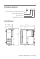
Catalog Number Explanation 1768 - M 04 SE Use this module with a 1768 CompactLogix controller Use this module for motion control Control up to 4 drives Control SERCOS interface drives Product Dimensions 56.68 mm (2.23 in.) 105.1 mm (4.14 in.) 100.5 mm (3.96 in.) 34.5 mm (1.36 in.) 132.015 mm (5.2 in.) 118 mm (4.65 in.
Minimum Spacing Plan for this minimum spacing from enclosure walls, wireways, and other equipment. 105 mm (4 in.) 90 mm (3.54 in.) 90 mm (3.54 in.) 105 mm (4 in.
What You Need IMPORTANT This product is grounded through the DIN rail to chassis ground. Use zinc plated yellow-chromate steel DIN rail to assure proper grounding. The use of other DIN rail materials (e.g. aluminum, plastic, etc.) that can corrode, oxidize, or are poor conductors, can result in improper or intermittent grounding. Secure DIN rail to mounting surface approximately every 200 mm (7.87 in.) and use end-anchors appropriately.
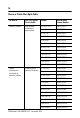
Choose a Plastic Fiber Optic Cable For Use In Use This Type of Plastic Cable Length Allen-Bradley Catalog Number Electrical cabinet Non-jacketed (chlorinated polyethylene) 0.1 m (5.1 in.) 2090-SCEP0-1 0.2 m (7 in.) 2090-SCEP0-2 0.3 m (1 ft) 2090-SCEP0-3 1 m (3.2 ft) 2090-SCEP1-0 Normal environments outside of an electrical cabinet Standard jacket (polyvinyl chloride) 3 m (9.8 ft) 2090-SCEP3-0 5 m (16.4 ft) 2090-SCEP5-0 8 m (26.2 ft) 2090-SCEP8-0 10 m (32.
For Use In Use This Type of Plastic Cable Length Allen-Bradley Catalog Number Harsh environment Nylon jacketed 0.1 m (4 in.) 2090-SCNP0-1 0.3 m (1 ft) 2090-SCNP0-3 0.9 m (2.9 ft) 2090-SCNP0-9 1 m (3.2 ft) 2090-SCNP1-0 3 m (9.8 ft) 2090-SCNP3-0 5 m (16.4 ft) 2090-SCNP5-0 8 m (26.2 ft) 2090-SCNP8-0 10 m (32.8 ft) 2090-SCNP10-0 15 m (49.2 ft) 2090-SCNP15-0 20 m (65.
Install Your Modules IMPORTANT Do not use both screws and DIN rail to mount the modules. It is possible to break the mounting tabs off if you screw the modules to the panel while they are on DIN rail. If You Are Using Screws to Mount Your Modules The steps in these instructions show how to mount the modules on DIN rail. If you are using screws instead of DIN rail, make these changes to the instructions: 1. Follow the steps in Mount the Modules on the DIN Rail to connect the modules together. 2.
Mount the Modules on the DIN Rail 1 31595-M 2 31596 -M Publication 1768-IN005A-EN-P - December 2005
Mount the Modules on the DIN Rail — Continued 3 31597-M 4 bb a c Publication 1768-IN005A-EN-P - December 2005 31598 -M
Mount the Modules on the DIN Rail — Continued 5 6 a b c d 31600-M Publication 1768-IN005A-EN-P - December 2005
Mount the Modules on the DIN Rail — Continued 7 bb c aa Publication 1768-IN005A-EN-P - December 2005
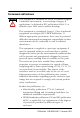
Connect the Fiber Optic Cables ATTENTION Under certain conditions, viewing the optical port may expose the eye to hazard. When viewed under some conditions, the optical port may expose the eye beyond the maximum permissible exposure recommendations.
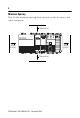
Confirm Your Installation Flashing Green Flashing Red and Green Flashing Green Power OUT L1 L2/N 31608-M See Troubleshoot the Module on page 21 if the lights are in other states.
Remove a Module 1 c — Off b — Off d f Power OUT L1 L2/N a 31602-M e 2 aa c Power OUT L1 L2/N 31607-M b Publication 1768-IN005A-EN-P - December 2005
Why Wait for the Lights to Turn Off Before I Remove a Module? After you turn off the power, wait for all of the lights on the power supply and controller to turn off before you disconnect any modules. • When you turn off the power, the controller writes its project to Flash memory. • The MEM SAVE light turns on while the controller writes its project to Flash memory. • If you don’t wait for the lights to turn off, you will lose your project. Care of Fiber Optic Cables Keep the fiber optic ports clean.
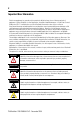
Troubleshoot the Module SERCOS Phase SERCOS Ring Status Module Status If the lights on the module look like this CP Ring OK Off Off Off Then do this • Make sure the module is connected and locked to the other modules. • Check the power supply and controller to make sure the backplane has power. Off Off Flashing Red Wait! Someone is updating the firmware of the module. Flashing Orange Off Flashing Green • Look for cables that are broken, unplugged, or in the wrong port.
If the lights on the module look like this Then do this CP Ring OK Flashing Green Flashing Green Flashing Green Check the configuration of the axes in RSLogix 5000 software. Solid Green Solid Green Flashing Green • Check the configuration of the drives in RSLogix 5000 software. • Check the motion group, drives, and axes for faults. Solid Green Solid Green Solid Green None — the axes are ready. Solid Green Solid Green Flashing Red Check the motion group and axes for faults.
Specifications CompactLogix SERCOS interface Module - 1768-M04SE Attribute Value Backplane Current (mA) 969 mA @ 5.2V dc Connections Consumed 3 Dimensions (HxWxD), Metric, Approx. Overall — 132.015 x 56.68 x 105.1 mm Installed and including mounting tabs — 132.015 x 34.5 x 105.1 mm Installed but not including mounting tabs — 118 x 34.5 x 105.1 mm Dimensions (HxWxD), Imperial, Approx. Overall — 5.2 x 2.23 x 4.14 in. Installed and including mounting tabs — 5.2 x 1.36 x 4.14 in.
CompactLogix SERCOS interface Module - 1768-M04SE (Continued) Attribute Value Fiber Optic Transmission Range Plastic cable — 1…32 m Mounting Screw Torque 1.16 Nm (10 lb-in.), using M4 or #8 screws Number of Axes, per Module, Max. 4 drives and 2 auxiliary feedback axes Power Dissipation 5.04 W Power Supply Distance Rating 2 — Keep the module within 2 slots from the power supply.
Environmental Specifications (Continued) Attribute Value 0…60 °C (32…140 °F) Non-Operating Temperature IEC 60068-2-1 (Test Ab, Un-packaged Non-operating Cold), IEC 60068-2-2 (Test Bb, Un-packaged Non-operating Dry Heat), IEC 60068-2-14 (Test Na, Un-packaged Non-operating Thermal Shock): -40…85 °C (-40…185 °F) Relative Humidity IEC 60068-2-30 (Test Db, Un-packaged Damp Heat): 5…95% non-condensing Vibration IEC 60068-2-6 (Test Fc, Operating): 5 g @ 10…500 Hz Operating Shock IEC 60068-2-27 (Test Ea
Environmental Specifications (Continued) Attribute Value Radiated RF Immunity IEC 61000-4-3: 10V/m with 1 kHz sine-wave 80%AM from 30…2000 MHz 10V/m with 200 Hz 50% Pulse 100%AM at 900 MHz 10V/m with 200 Hz 50% Pulse 100%AM at 1890 MHz 1V/m with 1 kHz sine-wave 80%AM from 2000…2700 MHz Enclosure Type Rating None (open-style) Certifications These certifications apply when the product is marked with them. See the Product Certification link at www.ab.
Additional Resources Publication Publication Number 1768 CompactLogix Power Supplies Installation Instructions 1768-IN001 CompactLogix Controller Installation Instructions 1768-IN004 CompactLogix EtherNet/IP Communication Module Installation Instructions 1768-IN002 CompactLogix Controllers User Manual 1768-UM001 Motion Modules in Logix5000 Control Systems User Manual LOGIX-UM002 Logix5000 Controller Motion Instructions Reference Manual 1756-RM007 1394 SERCOS Interface Multi Axis Motion Con
Rockwell Automation Support Rockwell Automation provides technical information on the web to assist you in using its products. At http://support.rockwellautomation.com, you can find technical manuals, a knowledge base of FAQs, technical and application notes, sample code and links to software service packs, and a MySupport feature that you can customize to make the best use of these tools.