
User guide

Rockwell Automation Publication 1768-UM002C-EN-P - April 2012 25
Install the Controller Chapter 2
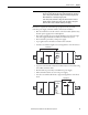
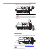
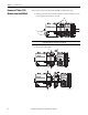
3. Slide the bus lever to the left to lock the modules together.
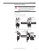
4. Attach the end cap by using the tongue and groove slots (a) and locking the
bus lever (b).
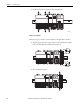
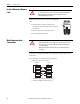
Confirm the Installation
After you have installed the controller and applied power, check that the PWR
and I/O PWR status indicators are solid green.
If the indicators are in any other state, see Troubleshoot System Power
on
page 120.
ATTENTION: When attaching I/O modules, it is very important that the
bus connectors are securely locked together for proper electrical
connection.
a.
b.
a.
Power
OUT
L1
L2/N